Q2: Draw Block diagram and the Q output from the waveform are applied to the S-R F.F with PRE and CLR, Assuming that the flip-flop is initially Reset? PRE O. CLR J
Q: For the state diagram below a sequential circuit has 2 D -flip-flops A(MSB) and B, one input…
A: From the state diagram prepare the excitation table, Current State (AB) Input (X) Next State…
Q: Q1 Design the circuit for the FSM described by the following state diagram. Use T-flip flop Reset…
A: The state diagram is shown below, From the above diagram,State A=000State B=001State C=010State…
Q: Question 3. Consider the JK- flip flop given below. J CLK K Q Fill in the below state table for the…
A: We need to find out truth table and state equation for jk flip flop .
Q: a) Complete the timing diagram for the D imput to a negative-edge triggered D flip-flop. Clock Q b)…
A: i have explained in detail
Q: Design a mod-6 counter using JK flip-flops that sequences through the following states: Q1Q2Q3 = 001…
A:
Q: Complete the following timing diagram (by completing the table) for a D flip-flop with falling edge…
A:
Q: 4- Draw the output waveform if the signal shown in Figure below is applied to inputs of J-K…
A:
Q: 9 Two edge-triggered J-K flip-flops are shown in The Figure. If the inputs are as shown, draw the Q…
A:
Q: Refer to the following figure, carefully, analyses the waveform of T flip-flop. What is the value of…
A: The T flip flop can be described as the single input version of the JK flip flop . So the truth…
Q: (4) Consider the following Edge Triggered D Type Flip-Flop with Set (S), Reset (R) and the D inputs.…
A:
Q: 4. (a) Design a 3-flip-flop counter which counts in the following sequence: АВС 000 010 111 100 110…
A:
Q: Derive the characteristic equation for complement output of J-K ff Draw the state diagram of J-K…
A:
Q: 1-The waveforms in the figure below are triggered D flip flop and a gated D latch (i.e., with enable…
A:
Q: Design the circuit that can count from 0 ,14,6, using the suitable Flip-Flop, showing the following…
A: Draw the excitation table. Present state Next state State Q2 Q1 Q0 State Q2(t+1)…
Q: output for the inputs in figure below Assume that Q starts LOW. 1) If the J-K flip-flop is positive…
A:
Q: Q3) The waveforms in Figure below are applied to the J, K, and clock inputs as indicated. Determine…
A: Truth Table of the JK flip flop
Q: b) Complete the state table D Flip-Flop D Qt+1 c) Write the state equations for D Flip-flop.
A:
Q: PROCEDURE Draw the circuit diagram of a decade counter using negative edge-triggered flip-flops. The…
A: The truth table for the JK flip-flop is given as: From the above table, It is seen that the output…
Q: Design a counter with JK flip-flops that counts primary numbers (2,3,5,7,11,13) in loop, show the…
A: This is a problem of counter design. The solution is shown in the next step
Q: (a) Determine the missing entries (i) to (vii) in Table Q3(a) of flip-flop excitation values…
A:
Q: HW_2 Ql: Show the complete logic of the FGI and FGO using: a- JK flip-flop. b- SR flip-flop. c- D…
A:
Q: Q2: Simplify A PN flip -flop has four operations. clear to zero. no change. complement. and set to…
A: Consider the given data: Here, PN flip-flop operations are, “Clear to 0” for the inputs PN=00 “No…
Q: Design a sequential circuit with two D flip-flops and two input x and y. When x=0, the state remains…
A: The state table is a tabular representation of the behavior of the system for different inputs and…
Q: Determine the D flip-flop excitation equations for the system represented with in the state…
A: Given states S0=00 s1=01 s2=10 s3=11
Q: Q2: Design asynchronous counter to count the sequence 3,4,5,6,7,8,9 and repeat using negative edge…
A: Synchronous counter will have individual clock for each flip flops. Asynchronous counter will have…
Q: Draw the diagram for Synchronous Sequential Circuit using JK Flip-Flops and the minimized equations
A: Solution- The given state diagram is shown below,
Q: DESIGN THE SYNCHRONOUS COUNTER WITH THE FOLLOWING STATE TRANSITION DIAGRAM. USE J-K FLIP FLOP IN THE…
A:
Q: Q1) Determine the Q and Q output waveforms of the (D flip-flops) in Figure below. Assume that the…
A:
Q: Determine the output states for this J-K flip-flop, given the pulse inputs shown:
A: JK flip flop truth table
Q: .. Define the Flip-Flop and what are the applications of Flip-flop?
A:
Q: 4- Draw the output waveform if the signal shown in Figure below is applied to inputs of J-K…
A: The behavior of a JK flipflop with active-low preset and clear inputs can be described as, The…
Q: Apply the waveforms shown below to a negative edge triggered D flip-flop and draw the Q waveform.…
A: To solve this problem one should know the truth table of D flip flop: When CLK is applied truth…
Q: S Full adder D Clk Clock
A: Draw the truth table for the full adder. Inputs Outputs x y Q S C=D 0 0 0…
Q: Determine the output Q of a positive edge-triggered JK flip-flop for the input waveforms depicted in…
A:
Q: How to make circuit diagram jk flip flops using these: Ja = BCD Ka=D Jb=CD Kb=CD JC=A'D Kc=A'D…
A:
Q: e) Complete the state table JK Flip-Flop J K Qt+1 f) Write the state equations for JK Flip-flop.
A: Given digital question
Q: show the waveforms for each flip-flop output with respect For the ring counter in Figure to the…
A: Truth table of the given ring counter Clock pulse Q0 Q1 Q2 Q3 Q4 Q5 Q6 Q7 Q8 Q9 0 1 0 0 0 0 0…
Q: The flip-flops in the drawing below are positive edge triggered D flip-flops. Let Q2, Q1, QO = 0,0,0…
A: D Flip-flop acts as a data transfer element. When an appropriate clock is provided, data at the…
Q: Consider a state diagram shown below. Implement this state diagram using T (toggle) flip- flops and…
A: For the given state diagram, 4 flip-flops will be required. The Excitation table can be constructed…
Q: Q2: Determine the Q output waveform if the inputs shown below are applied to a J-K flip flop that is…
A:
Q: 4- Draw the output waveform if the signal shown in Figure below is applied to inputs of J-K…
A: Latch is asynchronous device. It is level triggered device. It check input and change output…
Q: (4) Consider the following Edge Triggered D Type Flip-Flop with Set (S), Reset (R) and the D inputs.…
A: The Truth-Table of D type flip-flop is: Clock D Q Q¯ State 0 X Q Q¯ No change 1 X Q Q¯ No…
Q: QI/ Design a full adder circuit using a decoder or a multiplexer in your design: Q2/ What is the…
A:
Q: The flip-flops in the drawing below are positive edge triggered D flip-flops. Let Q2, Q1, Q0 = 0,…
A: A positive edge-triggered D flip-flop copies the data from the input to output at the rising edge of…
Q: The flip-flops in the drawing below are positive edge triggered D flip-flops. Let Q2, Q1, Q0 = 0, 0…
A: A positive edge-triggered D flip-flop will give the input sampled at the rising edge of the clock…
Q: Q1: For the J-K flip-flop, determine the Q output for the inputs in figure below Assume that Q…
A:
Q: Construct the Master-Slave J-K flip flop by using S-R flip flop. Also, discuss its application?
A:
Q: Q3 (a) Determine the missing entries (i) to (vii) in Table Q3(a) of flip-flop excitation values…
A:
Q: Show the digital circuit diagram, output waveforms and truth table of a modulo-5 up counter using…
A: Working principle:- It is very simple . Modulo-5 up counter means that counter should count from 0…
Q: 3. The waveforms shown in Figure below are applied to a negative edge-triggered JK flip- flop. The…
A: In this question, We need to draw the output waveform of the jK filp flop. We know the output of…
No plagarism please!
Correct and detailed answer will be Upvoted else downvoted. Thank you!
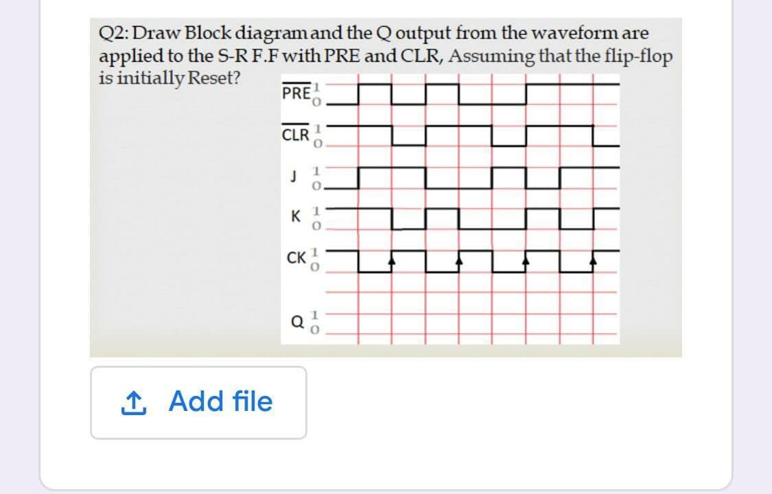
Step by step
Solved in 2 steps with 2 images
- Explain the difference between D-Latch and D flip flop with the help of diagram? If the ̅s and ̅R waveforms in Figure 2 are applied to the inputs of the latch as shown, determine the waveform that will be observed on the Q output. Assume that Q is initially LOW Kindly Handwrittenmake every flip flop out of every other type of flip flop. design derivations including Karnaugh maps JK out of D JK out of T JK out of SRWhat is NOR gate R-S flip flop?
- Q1. Differentiate: -• FPGA and CPLD• Edge trigger and Level Trigger• Octet and Quad• Synchronous and Asynchronous sequential circuits• D-Flip Flop and T-Flip FlopDraw a circuit for an asynchronous counter (using JK flip-flops and gates) that counts from decimal 0 to decimal 12and return back to decimal 0 (i.e. a modulo 12 counter). Show the status of each flip-flop on each of the thirteencounts.b) Figure 2.1 shows the input and the corresponding outputs of a flip-flop whereby QM and Q are taken from the Master latch and the Slave latch respectively. Give the full name of the flip-flop being used here and justify your answers. Use a block diagram for each latch, provide a circuit diagram of the flip-flop you have named.
- For the circuit below X=1,B=1,Y=1,C=1. What will be the next state for the flip-flop?A. set B. reset C. complement D. No change E. noneDesign a Up Down Counter by using JK flip flop and verify the output of your designed circuit onany random input. Provide the following information as well:1. State table2. State diagram3. State equations4. Complete circuit diagramComplete the blank In a J-K Flip Flop, if the input J=0 and K=1, then its output is...................?
- Design mealy machine sequence detector for 1000. Make state diagram, state table and circuit using JK and T flip flop.4 - what is the output for this Flip-Flop attached below?Design a\ Up Down Counter that counts from 0 to 7 up and 7 to 0 down by using JK flip flop and verify the output of your designed circuit on any random input. Provide the following information as well:1. State table2. State diagram3. State equations4. Complete circuit diagram