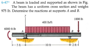
6-47 A beam is loaded and supported as shown in Fig. The beam has a uniform cross section and weighs 975 lb. Determine the reactions at supports A and B. 1000 lb 400 Ib/ft 6000 ft-lb B -3 ft -10 ft- 2 ft
Q: 6) The beam in the fig. below has built-in supports at both ends. Determine all the supports…
A:
Q: 6-32 A curved slender bar is loaded and supported as shown in Fig. Determine the reactions at…
A:
Q: Determine the internal forces (axial force, shearing force, and bending moment) at point J of the…
A: Draw the free-body diagram of the member AC.
Q: 6-91* A bar is supported by a ball-and-socket joint and two cables as shown in Fig. at support A…
A: Let point where downward force is acting be o Co-ordinates of points in question are A (0,0,0) B…
Q: В. ЗР (KN) P (kN) 3m 1m 2m 1m
A: force (P1)=3 KNforce (P2)=?hight (h)=3mlength(L1)=1mlength(L2)=2mlength(L3)=1m calculate the…
Q: The figure (not drawn to scale) shows a metallic cylindrical column submitted to a combined load:…
A:
Q: 6-61 Bar AB is supported in a horizontal position by two cables as shown in Fig. P6-61. Determine…
A: Draw the FBD for a better understanding of the problem.
Q: Use the method of sections to determine the forces in members BD, CD, and CE of the Warren truss…
A:
Q: Sample Problem: Determine the reactions for the beam loaded as shown in the figure below. 12 KN 15…
A:
Q: 6-36* A beam is loaded and supported as shown in Fig. The beam has a uniform cross section and a…
A: The free body diagram explains the problem
Q: For the truss loaded as shown in Figure 5, make calculations for the reactions at the support and…
A: Use Pythagoras theorem to calculate the distance AE. Calculate the angle θ.
Q: Calculate the support reactions at point A and B, and the forces at the hinges (C, D and E) of the…
A: The free-body diagram of the plane frame is shown below.
Q: Find the reactions for the supports on the frame below. P is 12 kN in the x direction, F is 24 kN in…
A: Given:-P=12 kNF=24 kNR= kNTo find:-Reaction on the frame
Q: 6-77* The bent bar shown in Fig. is supported with three brackets that exert only force reactions on…
A: Draw the free-body diagram of the bar.
Q: 6-40 An angle bracket is loaded and supported as shown in Fig. Determine the reactions at supports A…
A: at Pt. A angle bracket has a pin joint and at Pt. B it has roller support. The free body diagram of…
Q: 6-55* A rope and pulley system is used to support a body as shown in Fig. P6-55. Each pulley is free…
A: Consider the free body diagram of the pulley C as shown below, From the vertical equilibrium of…
Q: 6-43 Determine the reactions at supports A and B of the curved bar shown in Fig 30 50 Ib 6 in. 8…
A: Free-body diagram of the beam is given as, On taking equilibrium of forces in a horizontal…
Q: 6-95 A curved slender bar is loaded and supported as shown in Fig and B and the tension T in the…
A: Consider the free body diagram of the given figure as shown below.
Q: 3-5.9. Thể wheel loads on a small tractor crossing an 18-ft span are given in Fig. P-3-5.9.…
A: Given Data: Reaction at A is twice that the reaction at B, RA=2RB
Q: A rigid beam of negligible weight is supported by a hinge at A and a rocker at B as shown in the…
A: Given:F=16 KN
Q: the member is subjected to a distributed load and a point force as shown in the figure. Determine…
A:
Q: A 33 m beam has two supports. It overhangs each support by 5 m. The beam carries a point load of 600…
A: Given that: Length of the beam = 33 m It has two supports Overhang at both supports = 5 m 600 kN…
Q: 6-37 A structural member is loaded and supported as shown in Fig. tion and weighs 208 lb. Determine…
A: Given Data: The weight of the member is W = 208 lb. The free-body diagram of the member can be…
Q: P= 20i -14 %3D KN a) Calculate reaction ot A in KN the magnitude of tension m force member Calculate…
A:
Q: 8-30 A three-bar frame is loaded and supported as shown in Fig. moment transmitted by Determine the…
A: Given , Load = 900 N Let, Horizontal reaction at A = RHA N Vertical reaction at A = RVA N Vertical…
Q: -1m-- 1m ---lm Problem 3 A rigid rectangular beam has a weight of 20 kN acting at its center of mass…
A: G is the midpoint of CD; Taking the upper part from section X---X' Moment about C = 0; ∑M(C)=0 FBD…
Q: Q-2 Figure below shows a shaft that is loaded as given, essentially in bending. Bearings are located…
A: Given data Diameter of the shat at B = D = 45mm Dimeter of the shaft at C = 55mm Shaft is loaded at…
Q: Statics
A:
Q: 6-88* A bar is supported by a ball-and-socket joint, link, and cable as shown in Fig. at supports A…
A: Given: The force acting on the link AB, P = 2.5 kN The unit vector along CD,
Q: 6-62 A frame is loaded and supported as shown in Fig. P6-62. Determine the reactions at supports A…
A: Given data To determine the reactions at the supports A and E
Q: problem 1.3-9 solution plz....
A: Drawing the free body diagram of the truss as shown below –
Q: A pulley 1.2 m in diameter and supporting a load of 900 N is mounted at B on a horizontal beam…
A:
Q: 6-33 A beam is loaded and supported as shown in Fig. The beam has a uniform cross section and weighs…
A: Given Data: Force applied on beam is F = 2500 lb. Length of beam is L = 12 ft. The weight of beam…
Q: 4.6. Determine the force in member GH in the truss shown in Figure 4.37(Q4) by using a…
A:
Q: Find the reactions for the supports on the frame below. P is 24 kN in the y direction, F is 12 kN in…
A: Given:
Q: 6-35* A beam is loaded and supported as shown in Fig. The beam has a uniform cross section and…
A: Draw the free body diagram for the above problem.
Q: 10.4-9 The continuous frame ABC has a pin sup- port at A, roller supports at B and C, and a rigid…
A: Let us show the deflection in the beam due to the Moment at A and a redundant force at C, Due to…
Q: 4. Repeat problem 3 assuming that the column is made of wood for which E = 10 GPa. Ans. 81.34 mm
A: Given Force, F = 40 kN Length, L = 3 m E = 10 GPa Find Length, b
Q: 20 KN 20 KN 20 KN 20 KN/m 20 KN-m
A: To determine the reaction at point B.
Q: 6-47* A beam is loaded and supported as shown in Fig. The beam has a uniform cross section and…
A: Resolving the uniformly distributed load of magnitude 400 ×10= 4000 lb , which acts at the mid…
Q: Find reaction at C for a frame shown. using Consistent Deformations Method and Least Work Method 6 m…
A: Total Strain energy for the frame,U=Strain energy in semicircular portion+Strain energy in straight…
Q: Problem 3 (Pro 2.35 Textbook): The girder shown is supported by columns at A and B. Two smaller…
A:
Q: 6-80 Bar AC of Fig. at end C and is supported at end A with a ball-and-socket joint. The cable at B…
A: Consider the free body for the bar as shown below.
Q: 2. A 12- ft. bar of negligible weight rests in a horizontal position on the smooth inclines in…
A:
Q: -24 in. +6 in.- 2. Determine the horizontal and vertical components of reaction of the pin B. (Ib) 4…
A: Consider vertically upward & horizontally forward force as (+)ve and vertically downward &…
Q: Q3: A cantilever 4 m long is loaded with a uniformly distributed load of 5 kN/m run over a length of…
A: Given, cantilever beam , L = 4 m Uniformly distributed load over , w =5 KN/m over a length of 2 m…
Q: Determine the reaction of the supports in the figure below.
A: As per the given figure point, C is the internal hinge. So divide the beam in two parts from the…
Q: Pr4-30P) Draw shear force and bending moment diagrams of the beam. Hint : Calculate reaction forces.…
A:
Q: 6-78* The bent bar shown in Fig. two brackets that exert only force reactions on the bar. End C of…
A:
Q: 6-43* A cylinder is supported by a bar as shown in Fig P6-43. The weight of the cylinder is 100 lb…
A: Given:Wc=100 lbWb=20 lb
Trending now
This is a popular solution!
Step by step
Solved in 3 steps with 6 images
- Beams ABC and CD are supported at A,C, and D and are joined by a hinge (or moment release) just to the left of C. The support at A is a sliding support (hence reaction A = 0 for the loading shown below). Find all support reactions; then plot shear (F) and moment (M) diagrams. Label all critical Fand M values and also the distance to points where either F and/or M are zero.Beam ABC is supported by a tie rod CD as shown. Two configurations are possible: pin support at A and downward triangular load on AB or pin at B and upward load on AB. Which has the larger maximum moment? First, find all support reactions; then plot axial force (N), shear (V), and moment (M) diagrams for ABC only and label all critical N, V, and M values. Label the distance to points where any critical ordinates are zero.Repeat Problem 11.2-3 assuming that R= 10 kN · m/rad and L = 2 m.
- A long re Lai nine: wall is braced by wood shores set at an angle of 30° and supported by concrete thrust blocks, as shown in the first part of the figure. The shores are evenly spaced at 3 m apart. For analysis purposes, the wall and shores are idealized as shown in the second part of the figure. Note that the base of the wall and both ends of the shores are assumed to be pinned. The pressure of the soil against the wall is assumed to be triangularly distributed, and the resultant force acting on a 3-meter length of the walls is F = 190 kN. If each shore has a 150 mm X 150 mm square cross section, what is the compressive stressFor the beam shown below:Draw the free body diagram showing the reactions for each type of supportsknowing that the support on the left is a roller and on the right is a pinThe composite beam shown in the figure is connected by a pin in b.Determine the forces in A, B and C using the equations of equilibrium.Draw the free body diagram
- Given are the loadings of the beam in the figure. Assuming all bearings are frictionless. Beam AB is in equilibrium and it weighs 640 kN. a.) What is the weight W in kN? b.) What is the vertical reaction at A in KN?Calculate the support reaction forces at A and B for the beam? and the question stated in the attatched question.The composite beam shown in the figure is connected by a pin.in b.Determine the moments at A, B, and C and their forces using the equations of equilibrium.Draw the free body diagram.
- Calculate for the support reactionsP=51 -Plot the shear diagram-Plot the moment diagramKindly refer to the given figure below. determine the support reactions of the points A,B and C. Note: The support A is fixed and B is and internal hinge.The overhang beam below is supported by a pin support at A and a roller at B. The weight of the beam is 600 N/m. Draw the Free Body Diagram for this beam and apply the equilibrium equation to find the value of support reactions.