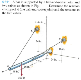
6-91* A bar is supported by a ball-and-socket joint and two cables as shown in Fig. at support A (the ball-and-socket joint) and the tensions in the two cables. Determine the reaction 14 in. 24 in. 16 in. 24 in. 22 in. 16 in. 18 in. 500 lb


Q: 6-32 A curved slender bar is loaded and supported as shown in Fig. Determine the reactions at…
A:
Q: A uniform cylinder is supported by a rigid bar AB ang cable BC as shown in the figure. If the stress…
A: Givenallowable stress in the cable σa=7.25ksi=7250 psidiameter of the cable, d=0.50in
Q: 6-79 Bar AB is used to support an 850-lb load as shown in Fig. and-socket joint. End B of the bar is…
A: Given that,
Q: 6-61 Bar AB is supported in a horizontal position by two cables as shown in Fig. P6-61. Determine…
A: Draw the FBD for a better understanding of the problem.
Q: Determine the force in each member of the loaded truss. All triangles are 3-4-5. Enter a positive…
A:
Q: 6-36* A beam is loaded and supported as shown in Fig. The beam has a uniform cross section and a…
A: The free body diagram explains the problem
Q: 6-77* The bent bar shown in Fig. is supported with three brackets that exert only force reactions on…
A: Draw the free-body diagram of the bar.
Q: w1 (kN/m) w2 (kN/m) A L The beam above is loaded by a trapezoidal distributed load that starts and…
A: Given data: w1=5 kN/mw2=2 kN/mL =6m Need to determine the magnitude of reaction force and couple.
Q: 6-40 An angle bracket is loaded and supported as shown in Fig. Determine the reactions at supports A…
A: at Pt. A angle bracket has a pin joint and at Pt. B it has roller support. The free body diagram of…
Q: 6-55* A rope and pulley system is used to support a body as shown in Fig. P6-55. Each pulley is free…
A: Consider the free body diagram of the pulley C as shown below, From the vertical equilibrium of…
Q: 6-47 A beam is loaded and supported as shown in Fig. The beam has a uniform cross section and weighs…
A: Given data: The weight of the beam is; w = 975 lb. The concentrated force acting at the right end of…
Q: Construct the reduced stiffness matrix of the shown truss, Fig. 3.Then determine the nodal…
A: L1=L2=2mL2=252mA1=A2=A3=80mm2E=200GpaE=200×103N/mm2
Q: 8-30 A three-bar frame is loaded and supported as shown in Fig. moment transmitted by Determine the…
A: Draw the F.B.D of the complete given frame.
Q: D F 4m E 3m 3m he pin-jointed frame work in the figure If a vertical concentrated load of 800KN…
A:
Q: 6-43 Determine the reactions at supports A and B of the curved bar shown in Fig 30 50 Ib 6 in. 8…
A: Free-body diagram of the beam is given as, On taking equilibrium of forces in a horizontal…
Q: 6-95 A curved slender bar is loaded and supported as shown in Fig and B and the tension T in the…
A: Consider the free body diagram of the given figure as shown below.
Q: Could you help me solve this question please? It is statics. Thanks.
A: Draw a free body diagram of the crane, Now, apply the equilibrium of force in the horizontal…
Q: 6-37 A structural member is loaded and supported as shown in Fig. tion and weighs 208 lb. Determine…
A: Given Data: The weight of the member is W = 208 lb. The free-body diagram of the member can be…
Q: Two horizontal bars ABC and DEF are rigid and originally horizontal and the links CE and DG are 1/4…
A:
Q: 1. A rigid horizontal bar of negligible mass is connected to two rods as shown in the figure. If the…
A:
Q: Figure Q1 shows bar ABCD attached to collars B and C which may move freely on its longitudinal axis.…
A:
Q: 4) Use the method of members to find the true magnitude and direction of the forces in the members…
A:
Q: · 400 mm- 1. A block with a mass of 150-kg is supported by a cable which passes over a 150-mm…
A: Given data: - The mass of the block is m = 150 kg. The distance between AB is h = 450 mm. The…
Q: 3. The weight W= 300 lb hangs from the cable which passes over the smooth pulley at F as shown in…
A:
Q: -1m 1m Ql: A: Draw a Free-Body Diagram of the bars AD and BC shown in the figure. Assume all hinges…
A:
Q: 6-88* A bar is supported by a ball-and-socket joint, link, and cable as shown in Fig. at supports A…
A: Given: The force acting on the link AB, P = 2.5 kN The unit vector along CD,
Q: 4 - For the given frame and loading, find the reactions at supports A and E. The pin and slot…
A: Draw the free-body diagram of the beam.
Q: 6-33 A beam is loaded and supported as shown in Fig. The beam has a uniform cross section and weighs…
A: Given Data: Force applied on beam is F = 2500 lb. Length of beam is L = 12 ft. The weight of beam…
Q: 5. Cords are looped around a small spacer separating two cylinders each weighing 500lbs and pass as…
A:
Q: 2-12. For the truss shown in the figure, deter- mine the total elongation of the member BC due to…
A:
Q: 5 - The ring supports the 1000-N load and is held in position by the two cables attached to vertical…
A: Given Load, P = 1000 N
Q: 4.6. Determine the force in member GH in the truss shown in Figure 4.37(Q4) by using a…
A:
Q: 6-21 The 6-m pole shown in Fig. P6–21 supports a load P = 20 kN. The pole is supported by a…
A:
Q: Act on the structure in the figure The horizontal force is 2KN at the end D Find the reaction in the…
A:
Q: A circular plate with weight W B. Shaft AC is fixed and frictionless. -210 k lb acting at its…
A:
Q: Situation 4-A load of W 30 kN is lifted through a boom BCD as shown in the Figure LI L2 AP-4.10. The…
A: Draw the schematic diagram. Calculate the distance AB.
Q: The simple truss is loaded by a system of forces as shown in the figure. The truss is supported by a…
A:
Q: The simple truss is loaded by a system of forces as shown in the figure. The truss is supported by a…
A: for the given truss P1 = 40 kN and P2 = 20 kN To determine Force developed in member ED
Q: 1. A rigid horizontal bar of negligible mass is connected to two rods as shown in the figure. If the…
A:
Q: 6-47* A beam is loaded and supported as shown in Fig. The beam has a uniform cross section and…
A: Resolving the uniformly distributed load of magnitude 400 ×10= 4000 lb , which acts at the mid…
Q: The simple truss is loaded by a system of forces as shown in the figure. The truss is supported by a…
A: Given data: The magnitude of the force P acting on the truss is P = 800 lb.
Q: 9 Determine reactions in A and tension in cable as shown in figure? 300 KN 30 kN/m 20 kN/m mm Xal 2m…
A:
Q: 6-80 Bar AC of Fig. at end C and is supported at end A with a ball-and-socket joint. The cable at B…
A: Consider the free body for the bar as shown below.
Q: The uniform 300-lb bar AB carries a 500-lb vertical force at A. The bar is supported by a pin at B…
A:
Q: 6-65* The crane and boom shown in Fig. 12,000 lb and 600 Ib, respectively. When the boom is in the…
A: The weight of the crane is mc=12000 lb. The weight of the boom is mb=600 lb. The weight of the load…
Q: Act on the structure in the figure The horizontal force is 2KN at the end D Find the reaction in the…
A:
Q: Construct the reduced stiffness matrix of the shown truss, Fig. 3.Then determine the nodal…
A:
Q: 6-78* The bent bar shown in Fig. two brackets that exert only force reactions on the bar. End C of…
A:
Q: 6-43* A cylinder is supported by a bar as shown in Fig P6-43. The weight of the cylinder is 100 lb…
A: Given:Wc=100 lbWb=20 lb
Q: 6-65 The crane and boom shown in Fig. 12,000 lb and 600 lb, respectively. When the boom is in the…
A: Given: Weight of the crane and boom are 12000 lb and 600 lb. Load which is lifted is 3600 lb.


Trending now
This is a popular solution!

Step by step
Solved in 3 steps with 7 images

- Solve the preceding problem if the mass of the tailgate is MT— 11 kg and that of the crate is hic— 6S kg. Use dimensions H = 305 mm, L = 406 mm, dc= 460 mm, and dT= 350 mm. The cable cross-sectional area is At= 11.0 mm'. (a) Find the tensile Force T and normal stress T in each cable. (b) IF each cable elongatesA crane boom of mass 450 leg with its center of mass at C is stabilized by two cables AQ and BQ (Ae= 304 mm2 for each cable) as shown in the figure. A load P = 20 KN is supported at point D. The crane boom lies in the y-z plane. (a) Find the tension forces in each cable: TAQand TBQ(kN}. Neglect the mass of the cables, but include the mass of the boom in addition to load P. (b) Find the average stress (s) in each cable.Two separate cables AC and BC support a sign structure of weight W = 1575 lb attached to a building. The sign is also supported by a pin support at O and a lateral restraint in the '-direction at D. (a) Find the tension in each cable. Neglect the mass of the cables. (b) Find the average stress in each cable if the area of each cable is Ae= 0.471 in2.
- A horizontal bracket ABC consists of two perpendicular arms AB of a length 0.75 m and BC of a length 0,5 m. The bracket has a solid, circular cross section with a diameter equal to 65 mm. The bracket is inserted in a friction less sleeve at A (which is slightly larger in diameter), so it is free to rotate about the r0 axis at A and is supported by a pin at C Moments are applied at point C M{=1.5 kN -m in the x direction and A/3 = L0 kN-m acts in the — z direction. Considering only the moments Mxand M2, calculate the maximum tensile stress t, the maximum compressive stress crc* and the maximum in-plane shear stress Tmax at point />, which is located at support A on the side of the bracket at mid-heightA long re Lai nine: wall is braced by wood shores set at an angle of 30° and supported by concrete thrust blocks, as shown in the first part of the figure. The shores are evenly spaced at 3 m apart. For analysis purposes, the wall and shores are idealized as shown in the second part of the figure. Note that the base of the wall and both ends of the shores are assumed to be pinned. The pressure of the soil against the wall is assumed to be triangularly distributed, and the resultant force acting on a 3-meter length of the walls is F = 190 kN. If each shore has a 150 mm X 150 mm square cross section, what is the compressive stressA polyethylene tube (length L) has a cap that when installed compresses a spring (with under-formed length L1) by an amount ?? = (L1 = L). Ignore deformations of the cap and base. Use the force at the base of the spring as the redundant. Use numerical properties given in the boxes. (a) What is the resulting Force-in the spring, Fk? (b) What is the resulting Force in the tube, Ftl (c) What is the filial length of the tube, Lf? (d) What temperature change ?T inside the tube will result in zero force in the spring
- The piston in an engine is attached to a connecting rod AB, which in turn is connected to a crank arm BC (see figure). The piston slides without friction in a cylinder and is subjected to a force P (assumed to be constant) while moving to the right in the Figure. The connecting rod. with diameter d and length L, is attached at both ends by pins. The crank arm rotates about the axle at C with the pin at B moving in a circle of radius R. The axle at C, which is supported by bearings, exerts a resisting moment M against the crank arm. (a) Obtain a formula for the maximum permissible force Pallow. based upon an allowable compressive stress acin the connecting rod. (b) Calculate the Force Pallowfor the following data:A gondola on a ski lift is supported by two bent arms, as shown in the figure. Each arm is offset by the distance b = ISO mm from the line of action of the weight force W. The allowable stresses in the arms are 100 MPa in tension and 50 MPa in shear. If the loaded gondola weighs 12 kN, what is the minimum diameter roof the arms?A capped cast-iron pipe is compressed by a brass rod, as shown. The mil is turned until it is just snug, then add an additional quarter turn to pre-compress the cast-iron pipe. The pitch of the threads of the bolt ap = 52 mils (a mil is one-thousandth of an inch). Use the numerical properties provided. (a) What stresses a and arwill be produced in the cast-iron pipe and brass rod. respectively, by the additional quarter turn of the nut? (b) Find the bearing stress ahbeneath the washer and the shear stress t(in the steel cap.