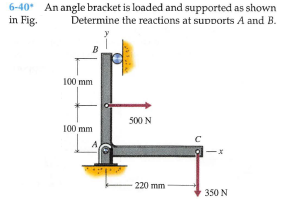
6-40 An angle bracket is loaded and supported as shown in Fig. Determine the reactions at supports A and B. B 100 mm 500 N 100 mm 220 mm 350 N


Q: 6-32 A curved slender bar is loaded and supported as shown in Fig. Determine the reactions at…
A:
Q: The frame shown in the figure is loaded as shown. (a) Draw the FBD for the frame. (b) Determine the…
A: The hinge at A gives the horizontal and vertical reaction The roller at E gives the horizontal…
Q: For the loading condition given in the figure, the reactions occurring in the A and B supports…
A:
Q: 3-5.7. A beam supports a load varying uniformly from an intensity w lb/ft at the left end to p lb/ft…
A:
Q: Answer the following questions: 1. Draw a Free Body Diagram with forces and reactions. 2. What are…
A:
Q: 6-32. Member CD has ball and socket connections at each end (Figure P6-32). Determine (a) the…
A: Please find the answer below
Q: Use matrix stiffness method to determine all reactions. Assume (1 is fixed, 2) is roller, and 3 is…
A: Use matrix stiffness method- Assuming 1 is fixed 2 is roller and 3 is pin ,E is constant
Q: Find the reactions for the supports on the frame below. P is 12 kN in the x direction, F is 24 kN in…
A:
Q: 6-91* A bar is supported by a ball-and-socket joint and two cables as shown in Fig. at support A…
A: Let point where downward force is acting be o Co-ordinates of points in question are A (0,0,0) B…
Q: 2-11. A wall bracket is constructed as showr in the figure. All joints may be considered pin…
A:
Q: 6-61 Bar AB is supported in a horizontal position by two cables as shown in Fig. P6-61. Determine…
A: Draw the FBD for a better understanding of the problem.
Q: The frame shown in the provide figure has Load F applied at point D. Answer the following questions…
A: Given: The applied force F is 600 N.
Q: 6-36* A beam is loaded and supported as shown in Fig. The beam has a uniform cross section and a…
A: The free body diagram explains the problem
Q: A member is supported by a roller (A) and a pin (B). A load of 12 kN is applied as shown. Find the…
A:
Q: For the pin-jointed truss in Figure (7), (a) determine the reactions at the supports at A and C, and…
A: given; (b) lets take force in BD menmer =F4 FBD at point D;…
Q: 6-77* The bent bar shown in Fig. is supported with three brackets that exert only force reactions on…
A: Draw the free-body diagram of the bar.
Q: 6-57 Pulleys A and B of the chain hoist shown in Fig. P6-57 are connected and rotate as a unit. The…
A:
Q: 6-55* A rope and pulley system is used to support a body as shown in Fig. P6-55. Each pulley is free…
A: Consider the free body diagram of the pulley C as shown below, From the vertical equilibrium of…
Q: 6-47 A beam is loaded and supported as shown in Fig. The beam has a uniform cross section and weighs…
A: Given data: The weight of the beam is; w = 975 lb. The concentrated force acting at the right end of…
Q: 3-5.18. The roof truss in Fig. P-3-5.18 (p. 96) is supported by a hinge at A and a horizontal roller…
A:
Q: 8-30 A three-bar frame is loaded and supported as shown in Fig. moment transmitted by Determine the…
A: Draw the F.B.D of the complete given frame.
Q: 3-5.9. Thể wheel loads on a small tractor crossing an 18-ft span are given in Fig. P-3-5.9.…
A: Given Data: Reaction at A is twice that the reaction at B, RA=2RB
Q: 6-37 A structural member is loaded and supported as shown in Fig. tion and weighs 208 lb. Determine…
A: Given Data: The weight of the member is W = 208 lb. The free-body diagram of the member can be…
Q: 8-30 A three-bar frame is loaded and supported as shown in Fig. moment transmitted by Determine the…
A: Given , Load = 900 N Let, Horizontal reaction at A = RHA N Vertical reaction at A = RVA N Vertical…
Q: Example ( 4-16) : The winch consists of a drum of radius ( 4 in. ), which is pie (B ) ( 3 in ).…
A:
Q: Problem 3 800 N The frame is loaded with the 800 N force as shown in the figure. Determine the…
A:
Q: 6-51 A lever is loaded and supported as shown in Fig. Determine the force exerted on the lever by…
A: Given: The length of AB is AB =12 in. The length of AC is AC= 6 in. Calculate the length of CD by…
Q: 6-88* A bar is supported by a ball-and-socket joint, link, and cable as shown in Fig. at supports A…
A: Given: The force acting on the link AB, P = 2.5 kN The unit vector along CD,
Q: 6-62 A frame is loaded and supported as shown in Fig. P6-62. Determine the reactions at supports A…
A: Given data To determine the reactions at the supports A and E
Q: 4 - For the given frame and loading, find the reactions at supports A and E. The pin and slot…
A: Draw the free-body diagram of the beam.
Q: D. C E. L, y= B L, w Find the magnitude of the horizontal and vertical components of the pin…
A:
Q: 6-33 A beam is loaded and supported as shown in Fig. The beam has a uniform cross section and weighs…
A: Given Data: Force applied on beam is F = 2500 lb. Length of beam is L = 12 ft. The weight of beam…
Q: Situation 15 - The truss shown in Figure SP-3.3 is supported on roller at A and hinge at B. 35.…
A: 35. First, draw the free body diagram of the whole structure: Now to calculate the reaction force…
Q: QUESTION 3 The rigid body structure is loaded and supported (pin at A and roller at D) as shown in…
A:
Q: 4.6. Determine the force in member GH in the truss shown in Figure 4.37(Q4) by using a…
A:
Q: Find the reactions for the supports on the frame below. P is 24 kN in the y direction, F is 12 kN in…
A: Given:
Q: 1. Figure Q1 shows members ABD and CDE which are pin-jointed at D to form a structure to hold a…
A:
Q: 4/116 The shipboard erane is supporting a load of 4 tons in the position shown where 6- 30°. The…
A:
Q: Problem 1 (4-37). If the supports at A and C are flexible and have a stiffness k, determine the…
A:
Q: A beam is loaded and supported as shown in Fig. P6-39. The beam has a uniform cross section and…
A:
Q: 6-47* A beam is loaded and supported as shown in Fig. The beam has a uniform cross section and…
A: Resolving the uniformly distributed load of magnitude 400 ×10= 4000 lb , which acts at the mid…
Q: Find reaction at C for a frame shown. using Consistent Deformations Method and Least Work Method 6 m…
A: Total Strain energy for the frame,U=Strain energy in semicircular portion+Strain energy in straight…
Q: 6-80 Bar AC of Fig. at end C and is supported at end A with a ball-and-socket joint. The cable at B…
A: Consider the free body for the bar as shown below.
Q: 6-65* The crane and boom shown in Fig. 12,000 lb and 600 Ib, respectively. When the boom is in the…
A: The weight of the crane is mc=12000 lb. The weight of the boom is mb=600 lb. The weight of the load…
Q: 3-5.15. A pulley of 1-ft radius, supporting a load of 500 lb, is mounted at B on a horizontal beam…
A:
Q: Determine the reaction of the supports in the figure below.
A: As per the given figure point, C is the internal hinge. So divide the beam in two parts from the…
Q: 6-78* The bent bar shown in Fig. two brackets that exert only force reactions on the bar. End C of…
A:
Q: 6-43* A cylinder is supported by a bar as shown in Fig P6-43. The weight of the cylinder is 100 lb…
A: Given:Wc=100 lbWb=20 lb
Q: 3-5.6. The weight of the trapezoidal block is hown in Fig. P-3-5.6. The ground reaction varies…
A:


Trending now
This is a popular solution!

Step by step
Solved in 2 steps with 4 images

- The inclined beam represents a ladder with the Following applied loads: the weight (W) of the house painter and the distributed weight (u) of the ladder itself. Find support reactions at A and B: then plot axial force (N), shear (V), and moment (M) diagrams. Label all critical N, V, and M values and also the distance to points where any critical ordmates are zero. Plot N, V, and M diagrams normal to the inclined ladder. Repeat part (a) for the case of the ladder suspended from a pin at B and traveling on a roller support perpendicular to the floor at A.An idealized column is composed of rigid bars ABC and CD joined by an elastic connection with rotational stiffness ßRIat C. There is a roller support at B and an elastic support at D with translationa1 spring stiffness ß and rotational stiffness ßR2. Find the critical buckling loads for each of the two buckling modes of the column. Assume that L = 3 m, ß = 9 kN/m, and ßR]= ßR1= ßL2. Sketch the buckled mode shapes.The frame ABC consists of two members AB and BC that are rigidly connected at joint B, as shown in part a of the figure. The frame has pin supports at A and C. A concentrated load P acts at joint B, thereby placing member AB in direct compression. To assist in determining the buckling load for member AB, represent it as a pinned-end column, as shown in part b of the figure. At the top of the column, a rotational spring of stiffness ßRrepresents the restraining action of the horizontal beam BC on the column (note that the horizontal beam provides resistance to rotation of joint B when the column buckles). Also, consider only bending effects in the analysis (i.e., disregard the effects of axial deformations). (a) By solving the differential equation of the deflection curve, derive the buckling equation for this column: RLEI(kLcotkL1)k2L2=0 in which L is the length of the column and EI is its flexural rigidity. (b) For the particular case when member BC is identical to member AB, the rotational stiff- ness ßRequals 3EI/L (see Case 7, Table H-2,Appendix H). For this special case, determine the critical load Pcr.
- Repeat Problem 11.2-3 assuming that R= 10 kN · m/rad and L = 2 m.A crane boom of mass 450 leg with its center of mass at C is stabilized by two cables AQ and BQ (Ae= 304 mm2 for each cable) as shown in the figure. A load P = 20 KN is supported at point D. The crane boom lies in the y-z plane. (a) Find the tension forces in each cable: TAQand TBQ(kN}. Neglect the mass of the cables, but include the mass of the boom in addition to load P. (b) Find the average stress (s) in each cable.A rectangular column with cross-sectional dimensions b and h is pin-supported at ends A and C (see figure). At mid-height, the column is restrained in the plane of the figure but is free to deflect perpendicularly to the plane of the figure. Determine the ratio h/b such that the critical load is the same for buckling in the two principal planes of the column.
- An idealized column is made up of rigid bars ABC and CD that are joined by a rotational elastic connection at C with stiffness ßR. The column has a roller support at B and a pin support at D. Find an expression for the critical load Pcr of the column.An idealized column consists of rigid bar ABCD with a roller support at B and a roller and spring support at D. The spring constant at D. is ß = 750 N/m. Find the critical load Pcrof the column.Pipe 2 has been inserted snugly into Pipe I. but the holes Tor a connecting pin do not line up; there is a gap s. The user decides to apply either force P:lo Pipe I or force P-, to Pipe 2, whichever is smaller. Determine the following using the numerical properties in the box. (a) If only P{is applied, find Pt{tips} required to close gap s; if a pin is then inserted and Ptremoved, what are reaction forces RAand RBfor this load case? (b) If only P2is applied, find P2{kips) required to close gap a; if a pin is inserted and P2removed, what are reaction forces R^ and RBfor this load case? (c) What is the maximum shear stress in the pipes, for the loads in parts (a) and (b)? (d) If a temperature increase IT is to be applied to the entire structure to close gaps{instead of applying forces Ptand P2), find the AT required to close the gap. If a pin is inserted after the gaphas closed, what are reaction forces .''.', and RBfor this case? (e) Finally, if the structure (with pin inserted) then cools to the original ambient temperature, what are reaction forces Rtand P
- Find the Controlling buckling load (kips) for the steel column shown in the figure. The column is Fixed at the base and free at the top and is made up of two C6 x 10.5 shapes that act together. Assume that E = 30,000 ksi and L = 14 ft.Three pinned-end columns of the same material have the same length and the same cross-sectional area (see figure). The columns are free to buckle in any direction. The columns have cross sections as: (a) a circle, (b) a square, and (e) an equilateral triangle. Determine the ratios Pa: Pb: Pcof the critical loads for these columns.Find support reactions at 4 and Band then use the method of joints to find all member forces. Let b = 3 m and P = 80 kN.