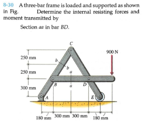
8-30 A three-bar frame is loaded and supported as shown in Fig. moment transmitted by Determine the internal resisting forces and Section aa in bar BD. 900 N 250 mm 250 mm 300 mm E 300 mm 300) mm 180 mm 180 mm


Q: 6-32 A curved slender bar is loaded and supported as shown in Fig. Determine the reactions at…
A:
Q: 8.5-20 For purposes of analysis, a segment of the crank- shaft in a vehicle is represented as shown…
A:
Q: 6-32. Member CD has ball and socket connections at each end (Figure P6-32). Determine (a) the…
A: Please find the answer below
Q: A bicycle chain consists of a series of small links, where each is 12 mm long between the centres of…
A:
Q: Find the reactions for the supports on the frame below. P is 12 kN in the x direction, F is 24 kN in…
A:
Q: 1.6-4 The inclined ladder AB supports a house painter (82 kg) at C and the self weight (q = 36 N/m)…
A:
Q: 2. The steel compression link shown in the figure has a rectangular cross section and supports an…
A:
Q: A punch press has sufficient capacity to punch six holes 26 mm in diameter in a 20-mm boiler plate.…
A: Given, Number of holes to be punched = n = 6 Diameter of holes = D = 26 mm Thickness of holes = t =…
Q: 3-84* The cantilevered bar in the figure is made from a ductile material and is statically loaded…
A: Ans.(a) . Bending stress and pansverse stress is will bemaximum at the outer surface(spear stress…
Q: PROBLEM: 3 A helical spring made of C50 steel has an outside diameter of 91 mm and a wire…
A:
Q: Example 6 1-38: Link BC is 6 mm thick, has a width w = with a 480 MPa ultimate strength in tension.…
A:
Q: 11.3-18 A long slender column ABC is pinned at ends A and C and compressed by an axial force P (see…
A:
Q: 3) Figure - 3 illustrates a type of engineering chain used for conveying applications. All…
A:
Q: 13. Buckling of Columns EXAMPLE 3 An aluminum column of length L and rectangular cross-section has a…
A:
Q: a) The material is 2024-T4 aluminum with a yield strength of 47 ksi b) The rod length L=6 in and arm…
A:
Q: Situation 4 - A load of W = 30 Li L2 kN is lifted through a boom BCD as shown in the Figure AP-4.10.…
A: Draw sketch to determine angle using properties of triangles In triangle ABD Angle ADB = 30o (sum…
Q: 8-30 A three-bar frame is loaded and supported as shown in Fig. moment transmitted by Determine the…
A: Draw the F.B.D of the complete given frame.
Q: SAMPLE PROBLEM 2: Assume that AE are equal for each rod Reqd: Internal forces for member AB, CD, EF…
A: Given Data: Length of the beam, L=0.8 m
Q: Circular steel bars will be used in the cage system in the figure. Accordingly, find the safety and…
A: The roller at D gives the vertical reaction and the hinge at G gives the horizontal and vertical…
Q: Two horizontal bars ABC and DEF are rigid and originally horizontal and the links CE and DG are 1/4…
A:
Q: 1. A rigid horizontal bar of negligible mass is connected to two rods as shown in the figure. If the…
A:
Q: 8.5-20 For purposes of analysis, a segment of the crank- shaft in a vehicle is represented as shown…
A: The at the fixed support is showing below - M1 moment is due to the compressive load acting in the…
Q: -1m 1m Ql: A: Draw a Free-Body Diagram of the bars AD and BC shown in the figure. Assume all hinges…
A:
Q: 8.5-20 For purposes of analysis, a segment of the crank- shaft in a vehicle is represented as shown…
A: The loading at which upper shaft is fixed is showing below – M1 moment is due to the compressive…
Q: A 14-in round wire coiled to form a conical spring with 10 effective coils & an outside diameter of…
A:
Q: 8.5-20 For purposes of analysis, a segment of the crank- shaft in a vehicle is represented as shown…
A:
Q: The space truss above is supported by ball-and-socket joint at points A, B, and E. A single force F…
A:
Q: A rigid body ABCKDE is in equilibrium under the e?ect of a set of loads as shown in the Figure. The…
A: Given data, Maximum intensity of distributed load, w = 15 kN/m Applied concentrated force, F1 = 30…
Q: 4.6. Determine the force in member GH in the truss shown in Figure 4.37(Q4) by using a…
A:
Q: Q3) A short stepped bar is shown in rigure below. The stiffness of the large section is 12 kN/mm and…
A: Given data: k1=12 kN/mk2=8 kN/mF=6kN Need to determine the displacements at node 2 and 3.
Q: -06 m - 3.1 The rigid bar af negligible weight is supported as shown in the figure If W= 80 kN,…
A: Answer: The temperature change of the assembly that will cause a tensile stress of 50 MPa in the…
Q: ,5-16 A rigid bar ABCD is pinned at end A and supported by two cables at points Band C. The cables…
A:
Q: A pin in a knuckle joint carrying a tensile load Fdeflects somewhat on account of this loading,…
A:
Q: 4. Repeat problem 3 assuming that the column is made of wood for which E = 10 GPa. Ans. 81.34 mm
A: Given Force, F = 40 kN Length, L = 3 m E = 10 GPa Find Length, b
Q: 1. A rigid horizontal bar of negligible mass is connected to two rods as shown in the figure. If the…
A:
Q: 11.3-18 A long slender column ABC is pinned at ends A and C and compressed by an axial force P (see…
A: Given:Flange section of column, W=250×67E=200 GPaL=5.5 mn=2.4
Q: Find reaction at C for a frame shown. using Consistent Deformations Method and Least Work Method 6 m…
A: Total Strain energy for the frame,U=Strain energy in semicircular portion+Strain energy in straight…
Q: 6-80 Bar AC of Fig. at end C and is supported at end A with a ball-and-socket joint. The cable at B…
A: Consider the free body for the bar as shown below.
Q: 4-2 A cantilever beam shown in Fig. P4-2 supports a uniform service (unfactored) dead load of 1…
A: for the given cantilever beam given the information we have breath of beam b=30 in overall depth…
Q: Consider the steel truss and member cross-section presented in figures below. All the members of the…
A:
Q: Example 4: The 2014-T6 aluminum strut is fixed between the two walls at A and B. If it has a 2 in by…
A: Let us draw the free body diagram of the shaft, From the table, we can find the relation of the…
Q: 3. A 15-AN truck having the wheel loads shown runs on top of a truss bridge as shown below. Assume…
A: given:
Q: Find reaction at C for a frame shown. using Consistent Deformations Method and Least Work Method A 6…
A:
Q: The steel bar has the original dimensions shown in the figure with b = 350 mm and c = 222 mm. If it…
A: It is given that
Q: 6-3 A solid circular shaft of 40 mm diameter is to be replaced by a hollow circular tube. If the…
A: Stress is defined as the force applied to a material divided by the cross-sectional area of the…
Q: The bell-crank mechanism shown below is supported by a single-shear pin connection at B and a roller…
A: Find the maximum load
Q: 105. For the truss shown in Fig. P-105, determine the cross-sec- tional areas of bars BE, BF, and CF…
A:
Q: A steel bar with a uniform cros section , is fixed at both ends. A load P=2.5 tips is applied at…
A: Give Data The load acting on the bar is: P=2.5 kips The cross sectional area is: A=8 in2 The modlus…
Q: truss is loaded as shown in the Figure. Assume AE = 10,000N. Which of the following most nearly…
A:


Trending now
This is a popular solution!

Step by step
Solved in 8 steps with 5 images

- The piston in an engine is attached to a connecting rod AB, which in turn is connected to a crank arm BC (see figure). The piston slides without friction in a cylinder and is subjected to a force P (assumed to be constant) while moving to the right in the Figure. The connecting rod. with diameter d and length L, is attached at both ends by pins. The crank arm rotates about the axle at C with the pin at B moving in a circle of radius R. The axle at C, which is supported by bearings, exerts a resisting moment M against the crank arm. (a) Obtain a formula for the maximum permissible force Pallow. based upon an allowable compressive stress acin the connecting rod. (b) Calculate the Force Pallowfor the following data:An idealized column is composed of rigid bars ABC and CD joined by an elastic connection with rotational stiffness ßRIat C. There is a roller support at B and an elastic support at D with translationa1 spring stiffness ß and rotational stiffness ßR2. Find the critical buckling loads for each of the two buckling modes of the column. Assume that L = 3 m, ß = 9 kN/m, and ßR]= ßR1= ßL2. Sketch the buckled mode shapes.The plane truss shown in the figure supports vertical loads F at joint D, 2F at joint C, and 3F at joint B. Each member is a slender circular pipe (E = 70 GPa) with an outside diameter of 60 mm and wall thickness of 5 mm. Joint B is restrained against displacement perpendicular to the plane of the truss. Determine the critical value of load variable F(kN) at which member BF fails by Eu1er buckling.
- A crank arm consists of a solid segment of length bxand diameter rf, a segment of length bltand a segment of length byas shown in the figure. Two loads P act as shown: one parallel to — vand another parallel to —y. Each load P equals 1.2 kN. The crankshaft dimensions are A] = 75 mm, fr> = 125 mm, and b3= 35 mm. The diameter of the upper shaft isd = 22 mm, (a) Determine the maximum tensile, compressive, and shear stresses at point A, which is located on the surface of the shaft at the z axis. (b) Determine the maximum tensile, compressive, and shear stresses at point B, which is located on the surface of the shaft at the y axisThe hoisting arrangement for lifting a large pipe is shown in the figure. The spreader is a steel tubular section with outer diameter 70 mm and inner diameter 57 mm. Its length is 2.6 m, and its modulus of elasticity is 200 GPa. Based upon a factor of safety of 2.25 with respect to Euler buckling of the spreader, what is the maximum weight of pipe that can be lifted? (Assume pinned conditions at the ends of the spreader.)An idealized column is composed of rigid bars ABC and CD joined by an elastic connection with rotational stiffness ßRat C. There is an elastic support at B with translational spring stiffness ß and a pin support at D. Find the critical buckling loads for each of the two buckling modes of the column in terms of ßL. Assume that ßR= ßL2. Sketch the buckled mode shapes.
- The figure shows an idealized structure consisting of two rigid bars with pinned connections and linearly elastic rotational springs. Rotational stiffness is denoted ßR. Determine the critical load Pcrfor the structure.A vertical pole of aluminum is fixed at the base and pulled at the top by a cable having a tensile force T(see figure). The cable is attached at the outer edge of a stiffened cover plate on top of the pole and makes an angle a = 20° at the point of attachment. The pole has length a = 2.5 m and a hollow circular cross section with an outer diameter d2= 280 mm and inner diameter d1= 220 mm. The circular cover plate has diameter 1.5d2 Determine the allowable tensile force Tallow in the cable if the allowable compressive stress in the aluminum pole is 90 MPa.An idealized column is made up of rigid bars ABC and CD that are joined by a rotational elastic connection at C with stiffness ßR. The column has a roller support at B and a pin support at D. Find an expression for the critical load Pcr of the column.
- Repeat Problem 2.3-4, but now include the weight of the bar. Sec Table 1.1 in Appendix I for the weight density of steel.A long slender column ABC is pinned at ends A and C and compressed by an axial force F (sec figure). At the midpoint B, lateral support is provided to prevent deflection in the plane of the figure. The column is a steel wide-flange section (W 250 × 67) with E = 200 GPa. The distance between lateral supports is L = 5.5 m. Calculate the allowable load P using a factor of safety n = 2.4, taking into account the possibility of Eu 1er buckling about cither principal centroidal axis (i.e., axis 1-1 or axis 2-2).Three round, copper alloy bars having the same length L but different shapes are shown, in the figure. The first bar has a diameter d over its entire length, the second has a diameter d over one-fifth of its length, and the third has a diameter d over one-fifteenth of its length. Elsewhere, the second and third bars have a diameter Id. All three bars are subjected to the same axial load P. Use the following numerical data: P = 1400 kN, L = 5m,d= 80 mm, E= 110 GPa. and v = 0.33. (a) Find the change in length of each bar. (b) Find the change in volume of each bar.