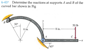
6-43 Determine the reactions at supports A and B of the curved bar shown in Fig 30 50 Ib 6 in. 8 in.- Jaso 45°


Q: 6) The beam in the fig. below has built-in supports at both ends. Determine all the supports…
A:
Q: Determine the total support reactions at A and 8 for the truss loaded below. -5 at 3 m- 15 m- 12 AN…
A:
Q: 10. Determine the total support reactions at A and B for the truss loaded below. -5 at 3 m 15 m 12…
A: The free-body diagram of the structure is given as,
Q: 6-79 Bar AB is used to support an 850-lb load as shown in Fig. and-socket joint. End B of the bar is…
A: Given that,
Q: Problem 4.30 4.30 The horizontal force P is applied to the handle of the puller. Determine che…
A: We have to find tension in figure
Q: 6-91* A bar is supported by a ball-and-socket joint and two cables as shown in Fig. at support A…
A: Let point where downward force is acting be o Co-ordinates of points in question are A (0,0,0) B…
Q: Solve the reinforcement using the method of nodes. Calculate the reactions and forces in the bars…
A: Consider the following FBD Reactions can be calculated by equilibrium equations Taking sum of…
Q: Calculate the internal reactions for the member shown at sections M-M and N-N [1.5 kN 0.6 m, 0.7 m…
A: A pin support will exert both horizontal and vertical components of reaction. The support A is pin…
Q: 6-52 Determine the reactions at supports A and B of the curved bar shown in Fie. 3 kN 4 kN 0.5 m Im…
A: Draw free body diagram for given beam Taking net moment about B to determine reactions at A
Q: 5-39. Determine the reactions at the supports A, C, and E of the compound beam. 12 kN 3 kN/m -3m- 6m
A:
Q: Calculate the horizontal reaction at the hinge support A of the equilibrium rigid body shown in the…
A: The free body diagram of the beam is a follows:
Q: 5. Calculate the reactions at the built-in support at C, neglecting the weights of the members. so0…
A:
Q: For the truss and loading shown below, please do the following: (17) a) Using the method of…
A:
Q: 6-40 An angle bracket is loaded and supported as shown in Fig. Determine the reactions at supports A…
A: at Pt. A angle bracket has a pin joint and at Pt. B it has roller support. The free body diagram of…
Q: 6-47 A beam is loaded and supported as shown in Fig. The beam has a uniform cross section and weighs…
A: Given data: The weight of the beam is; w = 975 lb. The concentrated force acting at the right end of…
Q: 6-103 A bar is loaded and supported as shown in Fig. End A of the bar is supported with a…
A: Draw the FBD for the above problem. Now write the vector expression for tension in the cable.
Q: Determine the reactions at A and B and the load required Q to hold bar AB in a horizontal position…
A:
Q: Using the method of sections, determine the forces in members BG, CI, and CD.
A: Given: A truss member To find: forces in members BG, CI, and CD
Q: 6-34 A beam is loaded and supported as shown in Fig. The beam has a uniform cross section and a mass…
A: Given mass of beam (m) = 180 kg To determine Reactions at support A
Q: 6-44 Determine the force exerted by the cable at B and the reaction at support A of the curved bar…
A: Given data as per question Force applied =850 N considering free body diagram of the system in Δ…
Q: Could you help me solve this question please? It is statics. Thanks.
A: Draw a free body diagram of the crane, Now, apply the equilibrium of force in the horizontal…
Q: 6-37 A structural member is loaded and supported as shown in Fig. tion and weighs 208 lb. Determine…
A: Given Data: The weight of the member is W = 208 lb. The free-body diagram of the member can be…
Q: Determine the reactions at the supports for the beam shown in Fig. 3.19(a).
A: In this problem we have one point load at C 160 kN and one UDL of 15 kNm over 6 m from A to B and…
Q: Determine the reactions at A and B and the load required Q to hold bar AB in a horizontal position…
A:
Q: 6-51 A lever is loaded and supported as shown in Fig. Determine the force exerted on the lever by…
A: Given: The length of AB is AB =12 in. The length of AC is AC= 6 in. Calculate the length of CD by…
Q: 6-88* A bar is supported by a ball-and-socket joint, link, and cable as shown in Fig. at supports A…
A: Given: The force acting on the link AB, P = 2.5 kN The unit vector along CD,
Q: 6-62 A frame is loaded and supported as shown in Fig. P6-62. Determine the reactions at supports A…
A: Given data To determine the reactions at the supports A and E
Q: 4 - For the given frame and loading, find the reactions at supports A and E. The pin and slot…
A: Draw the free-body diagram of the beam.
Q: Determine the force in members FD and DB of the frame in Figure 5. Also, find th horizontal and…
A: Since you have posted a multiple independent questions in a single question we will solve the first…
Q: 6-33 A beam is loaded and supported as shown in Fig. The beam has a uniform cross section and weighs…
A: Given Data: Force applied on beam is F = 2500 lb. Length of beam is L = 12 ft. The weight of beam…
Q: -200 mm - 350 mm B 200 mm C. A) Draw a Free Body Diagram of the bracket and cylinder together. The…
A:
Q: 5 - The ring supports the 1000-N load and is held in position by the two cables attached to vertical…
A: Given Load, P = 1000 N
Q: The member shown in Fig. 5-14a is pin connected at A and rests against a smooth support at B.…
A: Given data To determine The Horizontal and vertical component of reaction at A
Q: Use the Method of Joints to determine the force in each member of the truss shown in the figure.…
A: GIVEN DATA- A PLANE TRUSS GIVEN WE HAVE TO FIND FORCE IN ALL MEMBER
Q: In the given figure, support A is a roller and support B is a pin support. If P=15 kips, calculate…
A:
Q: *5-56. Two smooth tubes A and B, each having the same wright, W, are anepended from a eommon point O…
A: The free-body diagram of the system is: In triangle ACO, the angle OAC is: In triangle ACD, the…
Q: 5 m B 3 m 3m 80 kN 5 m
A: Draw the free body diagram of the system. Calculate the angle θ.
Q: 2) A cantilevered truss is loaded as shown below. Using method of sections determine the force in…
A:
Q: 6-46 A rope and pulley system is used to support a body as shown in Fig. the ropes are continuous…
A: Given data: Rope and pulley system mass of the body = 250 kg To determine:…
Q: 1. 2. P = 5 k V2P 4 -5'- 5' in
A: For the first figure :
Q: 6-89 A beam is supported by a ball-and-socket joint and two cables as shown in Fig. at support A…
A: B (0, 0, 6) C (-7, 0, 3) D (0, 11, 0) E (0, 6, 0) Taking moment about D, ΣMD = 0 ; - 11 j * Ax i -…
Q: -24 in. +6 in.- 2. Determine the horizontal and vertical components of reaction of the pin B. (Ib) 4…
A: Consider vertically upward & horizontally forward force as (+)ve and vertically downward &…
Q: Determine the horizontal and vertical components of the reaction at pin A and the reaction at roller…
A:
Q: 2nd 4m Mmax=6060 kN.m 6m -2ndº -1600KN.m 4m 2. From the moment diagram shown, assuming there are no…
A: (a) Draw the loading diagram from the given bending moment diagram.
Q: 6-78* The bent bar shown in Fig. two brackets that exert only force reactions on the bar. End C of…
A:
Q: 15° 400 N 600 N B 4 m -8m
A:
Q: Determine the support reactions at A and E of the truss shown below Assume support A is pin and…
A:
Q: 6-65 The crane and boom shown in Fig. 12,000 lb and 600 lb, respectively. When the boom is in the…
A: Given: Weight of the crane and boom are 12000 lb and 600 lb. Load which is lifted is 3600 lb.


Trending now
This is a popular solution!

Step by step
Solved in 3 steps with 6 images

- Can you Please Solve for Reaction @ Support A & B. Where EI constant.-7 Repeat Problem 2.3-5, but n include the weight of the bar. See Table I-I in Appendix I for the weight density of steel.The frame ABC consists of two members AB and BC that are rigidly connected at joint B, as shown in part a of the figure. The frame has pin supports at A and C. A concentrated load P acts at joint B, thereby placing member AB in direct compression. To assist in determining the buckling load for member AB, represent it as a pinned-end column, as shown in part b of the figure. At the top of the column, a rotational spring of stiffness ßRrepresents the restraining action of the horizontal beam BC on the column (note that the horizontal beam provides resistance to rotation of joint B when the column buckles). Also, consider only bending effects in the analysis (i.e., disregard the effects of axial deformations). (a) By solving the differential equation of the deflection curve, derive the buckling equation for this column: RLEI(kLcotkL1)k2L2=0 in which L is the length of the column and EI is its flexural rigidity. (b) For the particular case when member BC is identical to member AB, the rotational stiff- ness ßRequals 3EI/L (see Case 7, Table H-2,Appendix H). For this special case, determine the critical load Pcr.
- Find the controlling buckling load (kN) for the steel column shown in the figure. The column is pinned at top and bottom and is made up of two C 150 x 12,2 shapes that act together. Assume that E = 205 GPa and L = 6 m.A rectangular column with cross-sectional dimensions b and h is pin-supported at ends A and C (see figure). At mid-height, the column is restrained in the plane of the figure but is free to deflect perpendicularly to the plane of the figure. Determine the ratio h/b such that the critical load is the same for buckling in the two principal planes of the column.Repeat Problem 11.2-3 assuming that R= 10 kN · m/rad and L = 2 m.
- The inclined beam represents a ladder with the Following applied loads: the weight (W) of the house painter and the distributed weight (u) of the ladder itself. Find support reactions at A and B: then plot axial force (N), shear (V), and moment (M) diagrams. Label all critical N, V, and M values and also the distance to points where any critical ordmates are zero. Plot N, V, and M diagrams normal to the inclined ladder. Repeat part (a) for the case of the ladder suspended from a pin at B and traveling on a roller support perpendicular to the floor at A.Two steel shafts (G = 77.2 GPa) are connected to a coupling disk B and to fixed supports at A and C. Shaft BC is solid, while shaft AB is hollow with an inner diameter of 25 mm. Take T = 1.1 kN·m. Calculate the reaction at support A and CGiven are the loadings of the beam in the figure. Assuming all bearings are frictionless. Beam AB is in equilibrium and it weighs 640 kN. a.) What is the weight W in kN? b.) What is the vertical reaction at A in KN?
- The steel rod is shown in Figure has a diameter of 10 mm. It is fixed to the wall at A, and before it is loaded, there is a gap of 0.2 mm between the wall at B and the rod. Determine the reactions on the rod if it is subjected to an axial force of P = 20 kN. Neglect the size of the collar at C. Take Est = 200 GPa.Using the method of sections, determine the forces inmembers BG, CI, and CD. Express your answers in terms of P (e.g.FA= 0.5P)3.1 Use the concepts of moment and force equilibrium, find the reactions atpoint A (FAx and FAy) and point E (FEy).3.2 Find FBG first. Cut through BC, BG, and GF, consider the Left-Hand Side(LHS) section as a whole, find FBG by considering the Free-Body Diagram(FBD), and equilibrium of forces in the y-direction.3.3 Now find FCI and FCD. Cut through CD, CI, and HI, consider the RHSsection as a whole, find FCI by considering the FBD, and equilibrium offorces in the y-direction. Then, find FCD by taking moment at point I, andconsider the concept of moment equilibrium.the member is subjected to a distributed load and a point force as shown in the figure. Determine the support reactions at A and B.