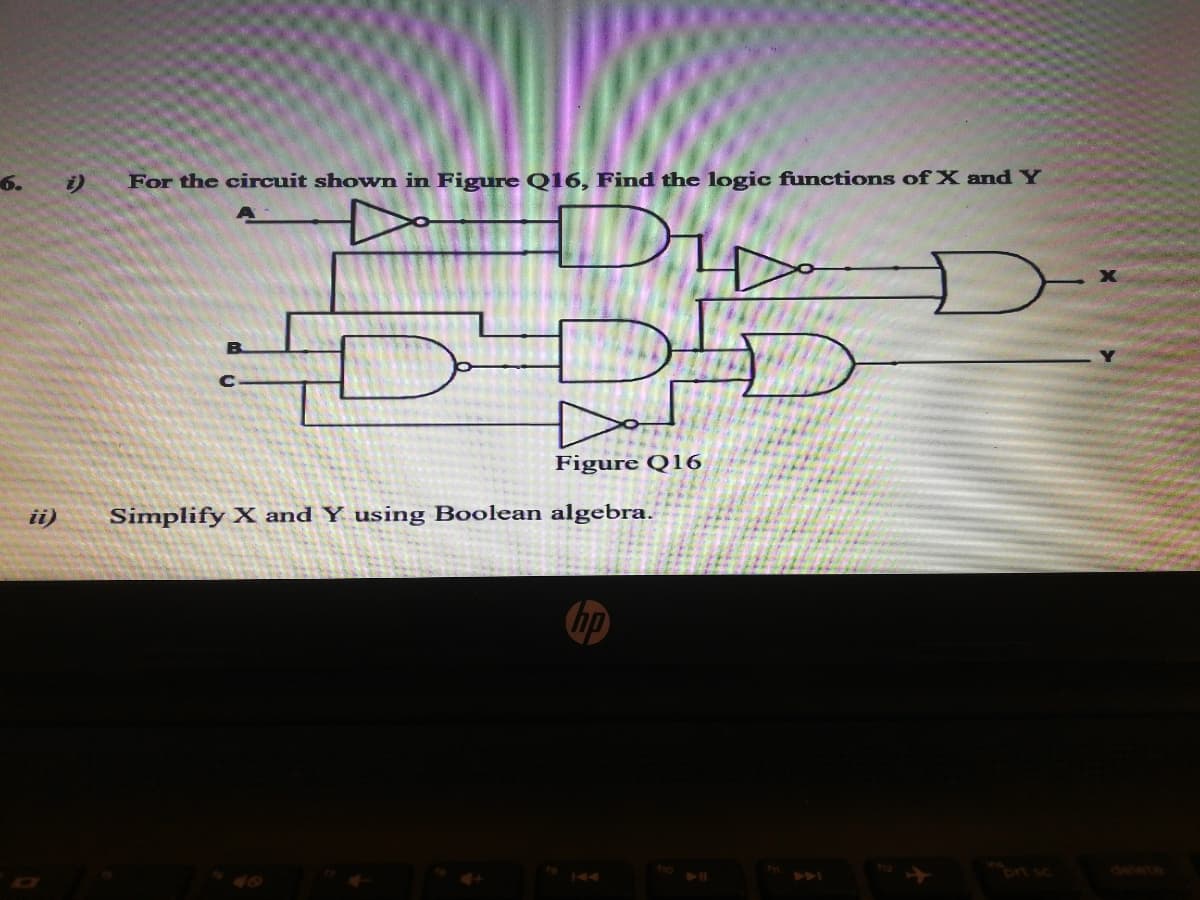
6. i) For the circuit shown in Figure Q16, Find the logic functions of X and Y Figure Q16 ii) Simplify X and Y using Boolean algebra.


Q: 3.(a) Make a truth table for this given logic gate, as shown in the figure. Show the steps. What is…
A: “Since you have asked multiple questions, we will solve the first question for you. If you want any…
Q: Q16. i) For the circuit shown in Figure Q16, Find the logic functions of X and Y Figure Q16 ii)…
A: So we have to find expression of x and y and simplify it.
Q: Design a counter that counts 1-2-3-5-7 Please explain the following:state diagram state table…
A:
Q: Q 5. Determine the expression of the given logic circuit and simplify it. (using De'Morgan's Jaw /…
A: For the given logic circuit, we need to determine the reduced Boolean expression using De'Morgan'…
Q: 3) Reduce (Simplify) the logic circuit expression A BU
A: Given logic circuit,
Q: 2. [This relates to part of the fast adder, with somewhat different and simpler notation.] Suppose…
A:
Q: 3.36 Draw the logic diagram of the digital circuit specified by the following Verilog description:…
A: Microprocessor and microcontrollers are used for data processing. Logic and control are used for…
Q: If the canonical sum of an n-input logic function is itself a minimal sum, how many literals are in…
A: We know, Canonical form is sum of products when it is the sum of min terms or we can say it is…
Q: Use Boolean algebra to simplify the following expression, then draw a logic gate circuit for the…
A: In this question , we will simplify given boolean expression and draw logic gate for simplified…
Q: 2. For each of the following expressions, construct the corresponding logic circuit, using AND and…
A: Logic circuits
Q: 1. As we saw in class, the range of a 4-bit binary number is 0000 to 1111 or in decimal, 0 to 15.…
A: As per our policy we can provide solution to first question only. As we have given , The range of 4…
Q: 2. Realize the following function F(A_B.C.D) =E(1,2,5,6,7,11) using a (a) 4-to-1 multiplexer, and…
A:
Q: i) For the logic diagram having NOR gates shown in Figure Q16i, predict the logic functions for Q. P…
A:
Q: Write the Boolean expression for the logic diagram given below and simplify it as much as possible…
A:
Q: (a) Design a ripple (Asynchronous) counter that counts from 5 to 13 using JK flip flops and any…
A:
Q: F a) Write the switching expression for the output, F(A,B,C,D) b) Simplify this switching function…
A: To simplify output, we will follow outputs from each gates and so on we can conclude final output F.…
Q: Designing A 4 Bit Operation Arithmetic Logic Unit
A: Arithmetic Logic Unit is a common operational unit with number of storage registers connected to it,…
Q: Q (A, B, C) = A̅ .B̅. C +A̅ .B. C + A .B. C̅ + A.B.C Karnaugh function given in the form Using the…
A:
Q: What is the one-bit half adder's purpose? What is the total number of inputs and outputs? What logic…
A:
Q: 3.36 Draw the logic diagram of the digital circuit specified by the following Verilog description:…
A: It is given that:
Q: Given the state diagram below, generate the (a)state table, (b)state equations, (c)output equation…
A: The given state diagram is: Let the input is X and the output is Y. Since the number of states is…
Q: Explain the working of 7-Segment Display. What it can display and how logic reduction is carried out…
A: According to the question, we need to explain the working of the 7-Segment Display. What it can…
Q: Minimize the combinational logic circuit in the following figure using Karnaugh's map only.…
A: K-MAP: K-Map is used to optimize the Boolean function by using grouping technique. It's also being…
Q: 2. Design the following Boolean function using appropriate Multiplexer and logic gates F(A, B, C, D)…
A: The given logic expression is:
Q: (i) Write a Boolean expression to represent the output of EACH logic gate. (ii) Next, simplify the…
A: The solution can be achieved as follows.
Q: Using 2-to-1 MUX and logic gates, build a logic circuit that compare between two binary number each…
A: Truth table for 2 bit comparator…
Q: 2. 2-to-1-Line Multiplexer Design a. Write the Condensed Truth Table of a 2-to-1 line Multiplexer b.…
A:
Q: . Design a 16 - to - 1 multiplexer using 4- to-1 multiplexer
A:
Q: Select a suitable example for for combinational logic circuit. O None of the given choices O Flip…
A: We know that flip flops are example of sequential logic circuit and PROM is an semiconductor memory…
Q: Q (A, B, C) = A̅ .B̅. C + A̅ .B. C + A .B. Obtain the function given as C̅ + A.B.C, simplified by…
A:
Q: Write the Boolean expression for the following logic gate circuit, then reduce that expression to…
A: There are two inputs for the last AND gate. First solve them separately. First Input is taken as…
Q: 1. Sketch logic diagram to implement F 2. Draw the truth table of function F 3. Use Boolean Algebra…
A:
Q: In your own words, what is a logic circuit?
A: As per Bartleby guidelines we are allowed to solve only one question, please ask the rest again.
Q: 1) If the sum of the 2-bit "AB" numbers and the 2-bit "CD" numbers is not odd, the logic circuit…
A:
Q: 3.5 Design a logic circuit from the following switch function using Boolean theory using only NOR…
A:
Q: Suppose we have two registers, Rl and R2, and between them we have a combinational logic circuit.…
A: Formula of maximum frequency; fc(max)=1Tmax Formula of Tmax; Tmax=tpcq+tpd+tsu+tccq+tcd+th…
Q: Simplify the following Boolean function using Karnaugh map. a. F(A, E, C, D)…
A:
Q: Implement the following logic expression by using universal NAND .(gate (A + BC ث إضافة ملف Simplify…
A:
Q: f. Y = (A + B)(B+C), please draw in logic circuit, and draw the ladder diagram, and then simplify.
A:
Q: How many 7400 ICs (minimum count) will be needed to execute the logic function F = A'B'C + AB'C' +…
A:
Q: Q16. i) For the circuit shown in Figure Q16, Find the logic functions of X and Y A Figure Q16 ii)…
A: We need to find the output of the given logic circuit and simplified expression of it.
Q: Design a logic circuit with four inputs and one output that will produce "1" in the output only if…
A: The solution is given below
Q: Design the logic circuit of a 3 to 8 line decoder with only NOR and NOTgates.
A:
Q: Given the following pullup circuit A-Design the pulldown circuitry B- What is the logic function…
A:
Q: Implement the Logic expression using only NOT and two-input NAND gates. A+B+C+D
A:
Q: Type the structural VHDL code that describes the expression F = AB' + A' B. %3D Assume that the VHDL…
A: We need to type the VHDL code that describes the expression F=AB'+A'B. We need to use Exps as the…
Q: Select a suitable example for combinational logic circuit. O a. None of the given choices O b.…
A: In this question we need to choose a correct option

Step by step
Solved in 4 steps with 2 images


- Consider two binary numbers where the first is made of three bits whichcan be represented by X, Y, and Z, while the second is two bits and isrepresented by A and B. Design a logic circuit that multiplies X Y Z timesA B, using two half adders, one full adder in addition to AND gates.Q (A, B, C) = A' .B'. C +A' .B. C + A.B.C' + A.B.C Obtain the simplified function with the Karnaugh Map method in terms of minterms and maxters separately. Set the output functions separately with logic gates with ANDNOT for minterms and ORNOT for maxterms.(a) Differentiate comparatively the analogue and digital representations. (b) If 33210= Xs then find the value of X. (c)1001011.0112 to equivalent decimal (d) What do you know about the logic gates? Explain the AND gate in details. 410 A
- Design a 4-bit arithmetic circuit, with two selection variables S1 and S0, that generates the arithmetic operations in the following table. Draw the logic diagram for a single bit stage. Note that B’ represents “Not B”. Draw the logic diagram for a single bit stagCreate the logic diagram of the two bits full adderQ (A, B, C) = A̅ .B̅. C + A̅ .B. C + A .B. Obtain the function given as C̅ + A.B.C, simplified by the Karnaugh Map method, in terms of minterms and maxters separately. Set the output functions separately with logic gates with AND NOT for minterms and OR for maxima.
- Design a circuit with logic gates that tell us if a number less than 10, codedin binary, it is either prime (1) or not (0). Minimum up to 16 combinations.True tableII. Boolean functionIII. Simplification procedure by any of the methodsa. Construct a Karnaugh map for the logic function D=ABC+ A ¯ BC+AB C ¯ +BC b. Find the minimum SOP expression and realize the function, using AND, OR, and NOT gates. c. Find the minimum POS expression and realize the function, using AND, OR, and NOT gates.1. Design a 16 - to - 1 multiplexer using 4- to-1 multiplexer. 2. Using K- Map, simplify the following Boolean expression : Y = Σ (1,3,5,7,9,10,11,13,14,) 3. Build the logic circuit for the following function using Programmable Logic Array (PLA). ?? = ??? + ??? + ??? + ??? ?? = ??? + ??? + ??? + ???
- Design 2 bits counter that count down by using T flip flop when input x =1 and counts upwhen x=0. Find the following1. Derive the state table2. Derive the K‐map simplifications.3. Draw the logic diagramUsing Boolean algebra theorems, simplify the logic expression above as far as possible. Create a Circuit Diagram for the new expression Then create a truthtable for the simplified circuitQ (A, B, C) = A̅ .B̅. C +A̅ .B. C + A .B. C̅ + A.B.C Karnaugh function given in the form Using the mapping method, you can use the simplified function separately in terms of minterms and maxters. obtain. Output functions with AND NOT for minterms and OR for maxters. Install separately with logic doors.