A beam is loaded as shown below. The vertical support reactions at points A and B are 300 kN and 375 kN respectively. The beam cross section is given with y = 0.207 m (centroid) and INA = 2.22 x 10⁴ m² (moment of inertia about its neutral axis). Using all this information, a) Draw the internal shear and moment diagrams for the beam. b) Determine the shear stress at section a-a, right above and below point E. Section a-a is positioned at 2 m along the beam and point E is shown on the cross section Hint: Find V(x=2m) from your shear diagram. AV=- w(x)ax Consider 0 ≤ x ≤ 3m. c) Determine the maximum tensile and compressive bending stresses in the beam. Hint: Find Mmax from your bending diagram. AM = V(x)dx Consider 0 ≤ x ≤ 3m. 300 kN/m diffing x=2 m- a 1.5 m- B 50 mm E 250 mm 150 mm 25 mm 150 mm 25 mm
A beam is loaded as shown below. The vertical support reactions at points A and B are 300 kN and 375 kN respectively. The beam cross section is given with y = 0.207 m (centroid) and INA = 2.22 x 10⁴ m² (moment of inertia about its neutral axis). Using all this information, a) Draw the internal shear and moment diagrams for the beam. b) Determine the shear stress at section a-a, right above and below point E. Section a-a is positioned at 2 m along the beam and point E is shown on the cross section Hint: Find V(x=2m) from your shear diagram. AV=- w(x)ax Consider 0 ≤ x ≤ 3m. c) Determine the maximum tensile and compressive bending stresses in the beam. Hint: Find Mmax from your bending diagram. AM = V(x)dx Consider 0 ≤ x ≤ 3m. 300 kN/m diffing x=2 m- a 1.5 m- B 50 mm E 250 mm 150 mm 25 mm 150 mm 25 mm

Elements Of Electromagnetics
7th Edition
ISBN:9780190698614
Author:Sadiku, Matthew N. O.
Publisher:Sadiku, Matthew N. O.
ChapterMA: Math Assessment
Section: Chapter Questions
Problem 1.1MA

Related questions

Question
Transcribed Image Text:2.
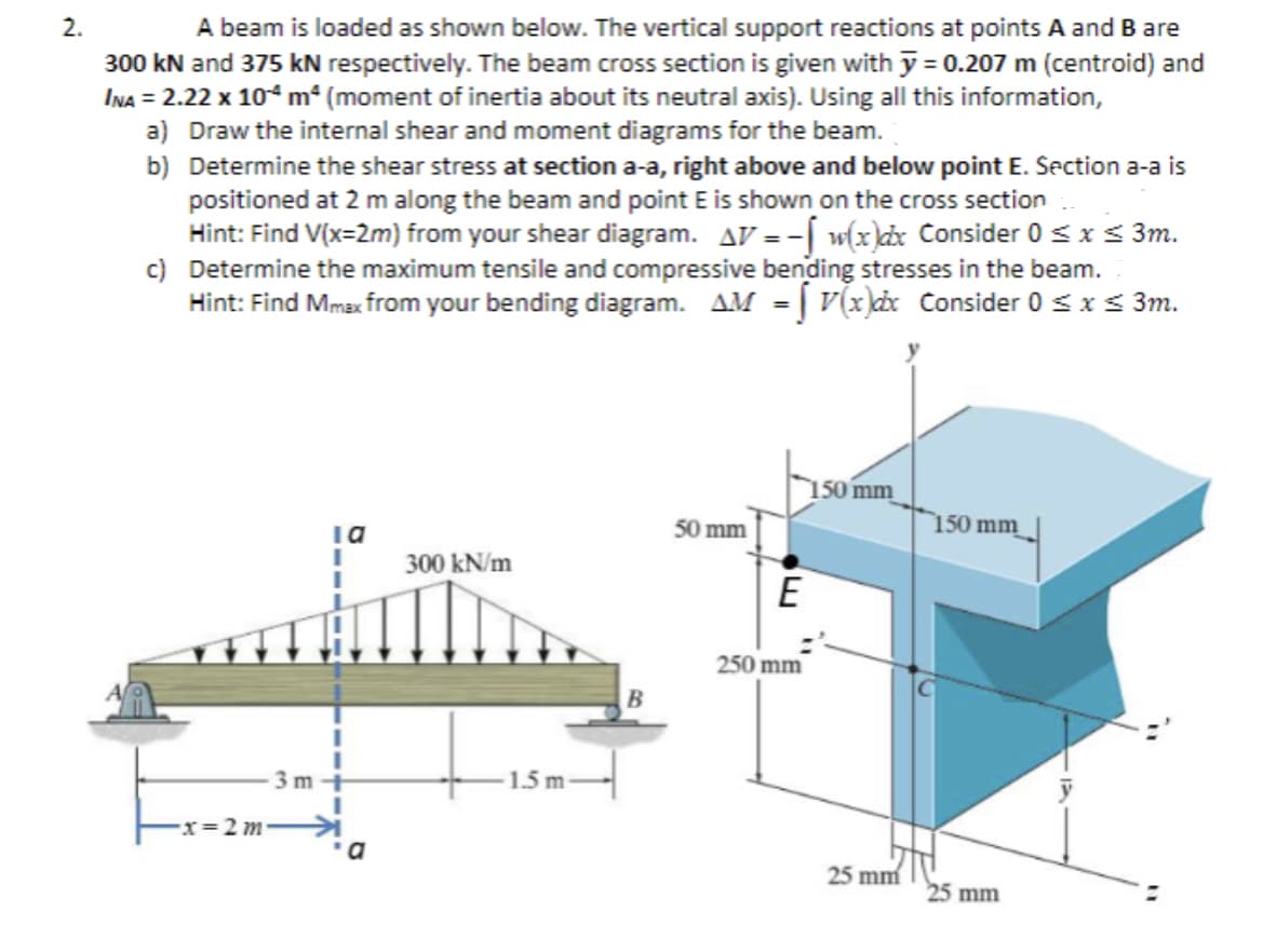
A beam is loaded as shown below. The vertical support reactions at points A and B are
300 kN and 375 kN respectively. The beam cross section is given with y = 0.207 m (centroid) and
INA = 2.22 x 10⁴ m² (moment of inertia about its neutral axis). Using all this information,
a) Draw the internal shear and moment diagrams for the beam.
b)
Determine the shear stress at section a-a, right above and below point E. Section a-a is
positioned at 2 m along the beam and point E is shown on the cross section
Hint: Find V(x=2m) from your shear diagram. AV=- w(x)dx Consider 0 ≤ x ≤ 3m.
c) Determine the maximum tensile and compressive bending stresses in the beam.
Hint: Find Mmax from your bending diagram. AM = V(x)dx Consider 0 ≤ x ≤ 3m.
3m
la
I
x=2 m 커
a
300 kN/m
1.5 m
B
50 mm
E
250 mm
150 mm
25 mm
150 mm
25 mm
IA
Expert Solution


Trending now
This is a popular solution!

Step by step
Solved in 9 steps with 6 images

Knowledge Booster


Learn more about
Need a deep-dive on the concept behind this application? Look no further. Learn more about this topic, mechanical-engineering and related others by exploring similar questions and additional content below.Recommended textbooks for you
Elements Of Electromagnetics
Mechanical Engineering
ISBN:
9780190698614
Author:
Sadiku, Matthew N. O.
Publisher:
Oxford University Press

Mechanics of Materials (10th Edition)
Mechanical Engineering
ISBN:
9780134319650
Author:
Russell C. Hibbeler
Publisher:
PEARSON

Thermodynamics: An Engineering Approach
Mechanical Engineering
ISBN:
9781259822674
Author:
Yunus A. Cengel Dr., Michael A. Boles
Publisher:
McGraw-Hill Education
Elements Of Electromagnetics
Mechanical Engineering
ISBN:
9780190698614
Author:
Sadiku, Matthew N. O.
Publisher:
Oxford University Press
Mechanics of Materials (10th Edition)
Mechanical Engineering
ISBN:
9780134319650
Author:
Russell C. Hibbeler
Publisher:
PEARSON
Thermodynamics: An Engineering Approach
Mechanical Engineering
ISBN:
9781259822674
Author:
Yunus A. Cengel Dr., Michael A. Boles
Publisher:
McGraw-Hill Education

Control Systems Engineering
Mechanical Engineering
ISBN:
9781118170519
Author:
Norman S. Nise
Publisher:
WILEY

Mechanics of Materials (MindTap Course List)
Mechanical Engineering
ISBN:
9781337093347
Author:
Barry J. Goodno, James M. Gere
Publisher:
Cengage Learning

Engineering Mechanics: Statics
Mechanical Engineering
ISBN:
9781118807330
Author:
James L. Meriam, L. G. Kraige, J. N. Bolton
Publisher:
WILEY