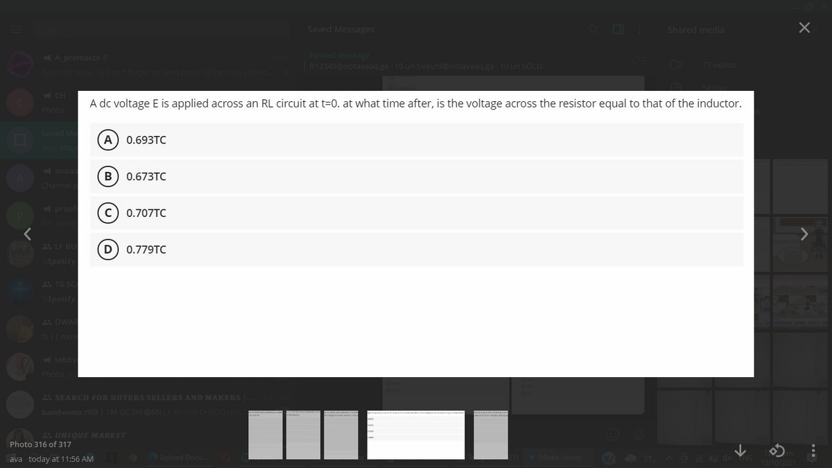
A dc voltage E is applied across an RL circuit at t=0. at what time after, is the voltage across the resistor equal to that of the inductor. A 0.693TC B) 0.673TC 0.707TC D) 0.779TC
Q: Q17. In a certain application, you need 0.05 µF. The only values available are 0.01 µF, which are…
A:
Q: An RL circuit has an emf of 5V, a resistance of 50Ω , an inductance of 1H and no initial current.…
A:
Q: If F(s) = (260/(S-+ 60S+ 3604)) and it is known that inductor had no current at t = 0, which of the…
A:
Q: In the circuit shown in figure, after the switch is open for a long time, it is closed at t=0. Now,…
A:
Q: For the given circuit the values of C1=9 µF, C2=11 µF, C3=9 µF and C4=11 µF A C1 С4 C3 C2 В The…
A: Equivalent Capacitance between A-B CT= 24.95 micro Farad
Q: or the following RLC circuit, powered by a direct current voltage source of! 0 V, answer with V or F…
A:
Q: For the given circuit the values of C1=8 µF, C2=13 µF, C3=8 µF and C4=12 µF A C1 C3 C2 C4 B. The…
A:
Q: Find the charge on the capacitor in an RLC series circuit where L = 2 H, R = 24Ω, C = 0.005 F, and…
A: GIVEN: L=2HR=24ΩC=0.005FE(t)=12sin 10t V FIND: Charge on the capacitor in RLC series…
Q: In the circuit shown, R=500Ω, L=0.64H, C=1 μF, and I=−1 A. Theinitial voltage drop across the…
A:
Q: Find the subsequent charge of the capacitor of an RLC circuit connected in series that has R= 185…
A: Solution- Given data, R = 185 ohm C = 1/300 F L = 22 H E(t) = 12 sin(t)
Q: A 20-µF capacitor is connected in parallel to the series connection of a variable resistor R and a…
A: Given that,A series connection of variable resistor and inductor is connected in parallel connection…
Q: (d) Find vc() and in(). (d) Find the energies in the inductor and capacitor at t = 0, wi(0) and…
A:
Q: R.
A: Part (4): It is assumed that the capacitor is charged by a battery of voltage, V0. After removing…
Q: The circuit below is at steady state before the switch closes att = 0. Find the voltage across the…
A:
Q: An RL circuit has an emf of 5V, a resistance of 50Ω, an inductance of 1 H and no initial current.…
A:
Q: R
A:
Q: Design a parallel RLC circuit having 100 W, 220 V source and a total impedance of 437.6993 ohms. The…
A: Impedance of circuit is 437.6993 ohms. Voltage across circuit is 220 V. the power dissipated in…
Q: An RLC series circuit has a 60-Hz, 120 V applied voltage. R = 75 N, XL = 100 N, and XC = 89 Q. What…
A: Given data: An RLC series circuit f=60 HzV=120 VR=75 ΩXL=100 ΩXC=89 Ω
Q: In the circuit below, the switch was turned to the 2 position at t=0 after being in the 1 position…
A: According to question:
Q: The circuit below is at steady state before the switch opens at t = 0. Find the current through the…
A:
Q: A capacitor in an RC circuit was allowed to discharge through a resistor. How long will it take to…
A: The initial energy of capacitor is given by, E1=q122C Final energy of capacitor should be, E2=q222C
Q: 2. A parallel RLC circuit is measured to have a Qo of 200. Determine the remaining component value…
A: In this question quality factor of parallel rlc circuit is given....We have to find out unknown…
Q: 9. The circuit is at steady state before the switch opens at time t = 0. The output of this circuit…
A:
Q: The voltage on 3 mH inductor is shown in * .figure. Find and draw the current i 15.0 t, ms -30.0
A: Given: Inductance L=3 mH From the voltage waveform, VL=15 V0<t<2 ms-30 V2<t<4 ms
Q: C. Multiple Choice. A series RLC circuit has a resistance of 7.5 Q, a capacitance of 10-2F, an…
A: Given R= 7.5 Ω L=1/6 =0.166 C =10-2 F E=12 V It is asked to find B2 constant value and final current…
Q: The resistor in the circuit shown is changed to 250 Ω. The initial energy stored is still zero. Find…
A: To do the circuit analysis the circuit be modified as by using a source transformation circuit we…
Q: 4. The circuit is in DC steady state at t =0". At t=0 the switch is opened. 24 V 0.25F
A: This question is from "Networks". Under which we are going to study about the transient response of…
Q: In the circuit shown above, the initial voltage across capacitor is 2 V and I is a unit step current…
A: The required parameters can be obtained by considering the state of the circuit at t=0 and after…
Q: In the circuit shown in figure, after the switch is open for a long time voltage across the…
A: We will use nodal analysis to find out the differential equation governing capacitor voltage. Using…
Q: The figure on the side is showing how the voltage on the Electric potential accross the capacitor…
A: The given graph between the voltage and time is the curve of a RC discharging circuit. In a RC…
Q: 1) You will be building an RLC circuit. However, the only inductor (L = 175 mH) and resistor (R =…
A: Given information: Value of resistor is R=232 Ω. Value of inductor is L=175 mH=175×10-3 H. Value of…
Q: In the circuit shown in figure, after the switch is open for a long time, it is closed at t=0. Now,…
A: Choose the correct options In the circuit.find the value of the voltage across the capacitor at time…
Q: Step response of series RLC. No energy is stored in the 100mH inductor or 0.4µF capacitor when the…
A:
Q: In the shown circuit, the capacitor is initially uncharged. The switch S is closed at time t=0. Find…
A:
Q: The switch in the given circuit has been closed for a long time, and it is opened at t=0, Find V.…
A: In this question, Find the voltage across the capacitor. Capacitor act as open circuit after long…
Q: A 20-µF capacitor is connected in parallel to the series connection of a variable resistor R and a…
A: This question belongs to circuit theory . It is based on the concept of equivalent impedance of the…
Q: he RC circuit shown find (a) the voltage on the capacitor and (b) the voltage on the resistor at t =…
A: Introduction: The DC Power Supply is linked to the capacitor, and current flows through the circuit.…
Q: 8. A series RL DC circuit needs 10 ms for the current to reach 90% of its steady state value.…
A: We need to find out time constant for the given circuit
Q: The voltage on 3 mH inductor is shown * .in figure. Find and draw the current i 15.0 t, ms -30.0
A: Given voltage across inductor is shown below. Given inductor value L=3mH. The current through…
Q: In a RC or RL circuit, the charge, current and potential difference grow and decay exponentially.…
A: In a RL or RC circuit, the parameters which are charge or current or potential difference are given…
Q: An AC bridge circuit the supply voltage is 20 V at 500 Hz. Arm AB is 0.25 µF pure capacitance; arm…
A:
Q: An uncharged capacitor C=5 µF is connected in a circuit as shown. The switch S is closed at t=0.…
A:
Q: 9. Determine the time constant of an RL circuit with a resistance R = 1.5 kohms and a 50mH inductor…
A:
Q: In a series RLC circuit, if the value of the pure capacitance is decreased as one-third the value of…
A: Right Answer option False
Q: An RL circuit with a 6-2 resistor and a 0.04-H inductor carries a current of 1 A at t=0, at which…
A:
Q: R www Vc For the given circuit above, the circuit values are as follows; L- 330 mH, C= 50 µF and R =…
A:
Q: Find the steady state current in the RLC circuits when R=18ohm ,L=1H,C=12.5×10^-3F and E = 820 cos…
A:
Q: Find the inductor current at t=150 ms if the voltage waveform below is applied to a 5 mH inductor.…
A:
Q: An RL circuit has an emf of 5V, a resistance of 50 Ω, an inductance of 1 H, and no initial current.…
A:
Trending now
This is a popular solution!
Step by step
Solved in 4 steps with 3 images
- * From the next TF, obtain ?p, %??, ?s and TrCompute the 8 – point DFT of x(n) = { 1,2,3,0,3,2,1,3}, using the following methods;(a) DIT – FFT method (b) DIF – FFT method (c) Phasor plot of twiddle factor to compute the DFTUrgent answer need Don't provide wrong solution. Here, R=4,K=3,L=7,M=3,N=5 Sub: Signal and linear system Dept:EEE
- Find (i) 11010111.110102 + 10001011.1010112 (iii) 11010.1102 x 1011.00112 (ii) 101101.112 – 11010.1012 (iv) 100101010.102 by 10102 (IX) Represent (-61)10 in a) Sign Magnitude form and b) Sign 2’s Complement formQ1 Minimize the following minterms using K-MAPY= m (0, 2, 5, 6, 7, 8, 10, 13, 15 )pleease have step by step solution for each part and explain. also i dont understand what to do with -3Db cutoff frequency.
- The second generation of mobile communication phones was ________.a) digitalb) analogc) semi analogd) radio frequencyii. Enhance data rate for GSM evolution (EDGE) is a ______ system, with a data rate of384kbps.a) 1 Gb) 2.5 Gc) 3.5 Gd) 4 Giii. This is due to reflection of radio signals by solid objects, which results in signals beingreceived along multiple paths.a) Infrared systemsb) Carrier sense multiple accessc) Multipath fadingd) Orthogonal frequency division multiplexingiv. Which of the following is the IEEE standard for Wi Max?a) 802.3b) 802.11c) 802.15d) 802.16can u answer this plsPerform addition on the given base-r number systems. 5138+ 23058 CAFE16 + FACE16 CB013 + 7AB13