(a) Figure 1 shows two bias circuits using bi-polar junction transistor (BJT). Assuming the value and are A kn, B kn and C kn respectively. i. Perform dc analysis on both circuits to obtain and for two different values of Beta which are = 70 and = 140. Assume = 15V and (kQ) is the sum of the last three digit your matric number (i.e., matric number 0123456789, value is 7 + 8 +9 = 24 kN). ( Co1, PO2, WK3, WP1) ' ii. Based on the analysis above, shows that the bias circuit in Figure 1(b) is more stable compared to the one in Figure 1(a). (C4, CO1, PO2, WK4, WP1, WP2) I (b) Illustrate the ac equivalent network for the circuit in Figure 1(b) by substituting the equivale circuit into the network. (C6, CO1, PO2, WK3, WP1) (c) Determine the following parameters,,, and using the equivalent circuit in part (b). Assume (C4, CO1, PO2, WK3, WP1) (d) If in the case of D kN, compute the difference in percentage (%) of values obtain for each of parameters in (c)ICA C01 PO2 WK3 WD1)
(a) Figure 1 shows two bias circuits using bi-polar junction transistor (BJT). Assuming the value and are A kn, B kn and C kn respectively. i. Perform dc analysis on both circuits to obtain and for two different values of Beta which are = 70 and = 140. Assume = 15V and (kQ) is the sum of the last three digit your matric number (i.e., matric number 0123456789, value is 7 + 8 +9 = 24 kN). ( Co1, PO2, WK3, WP1) ' ii. Based on the analysis above, shows that the bias circuit in Figure 1(b) is more stable compared to the one in Figure 1(a). (C4, CO1, PO2, WK4, WP1, WP2) I (b) Illustrate the ac equivalent network for the circuit in Figure 1(b) by substituting the equivale circuit into the network. (C6, CO1, PO2, WK3, WP1) (c) Determine the following parameters,,, and using the equivalent circuit in part (b). Assume (C4, CO1, PO2, WK3, WP1) (d) If in the case of D kN, compute the difference in percentage (%) of values obtain for each of parameters in (c)ICA C01 PO2 WK3 WD1)

Introductory Circuit Analysis (13th Edition)
13th Edition
ISBN:9780133923605
Author:Robert L. Boylestad
Publisher:Robert L. Boylestad
Chapter1: Introduction
Section: Chapter Questions
Problem 1P: Visit your local library (at school or home) and describe the extent to which it provides literature...

Related questions

Question
Transcribed Image Text:Question 1
Vcc
RC
Vcc
R1
Vo
В
RC
V;
Zo
t.
RB
Vo
E
I
C2
R2
Rɛ
CE
Zo
(b)
(a)
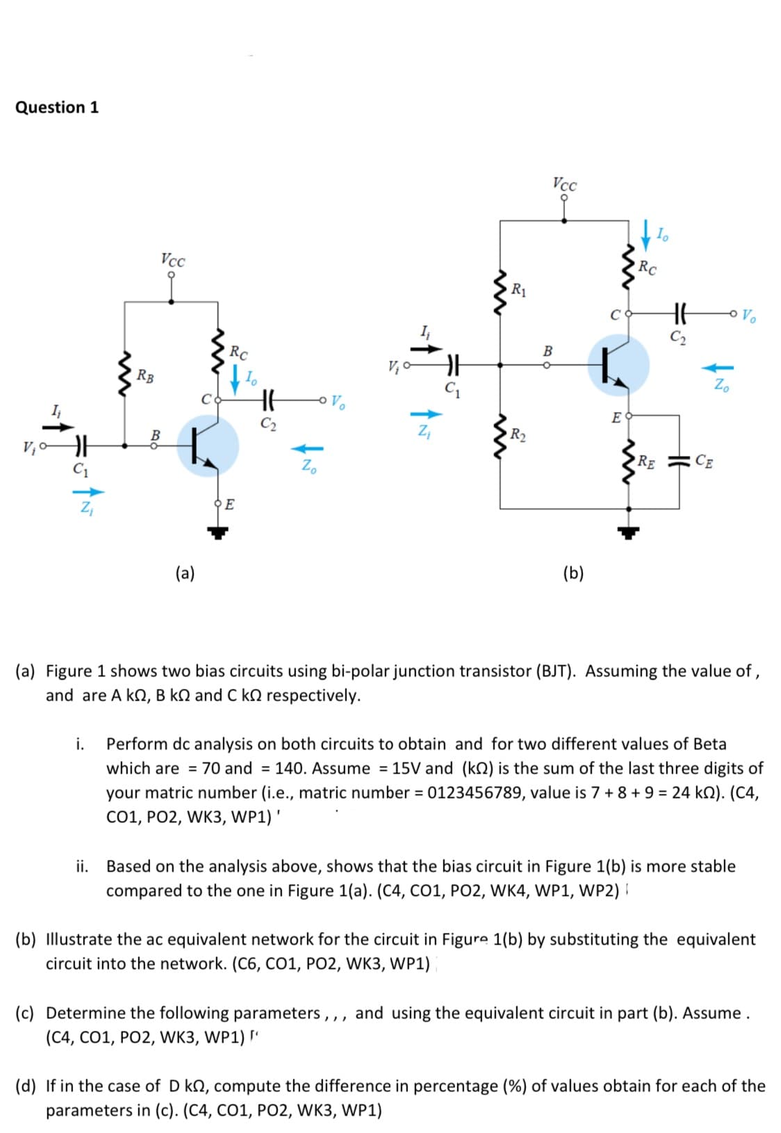
(a) Figure 1 shows two bias circuits using bi-polar junction transistor (BJT). Assuming the value of ,
and are A kn, B kN and C kn respectively.
i.
Perform dc analysis on both circuits to obtain and for two different values of Beta
which are = 70 and = 140. Assume = 15V and (kQ) is the sum of the last three digits of
your matric number (i.e., matric number = 0123456789, value is 7 + 8 + 9 = 24 kN). (C4,
Co1, PO2, WK3, WP1)'
ii.
Based on the analysis above, shows that the bias circuit in Figure 1(b) is more stable
compared to the one in Figure 1(a). (C4, CO1, PO2, WK4, WP1, WP2) I
(b) Illustrate the ac equivalent network for the circuit in Figure 1(b) by substituting the equivalent
circuit into the network. (C6, C01, PO2, WK3, WP1)
(c) Determine the following parameters,,, and using the equivalent circuit in part (b). Assume.
(C4, CO1, PO2, WK3, WP1) "
(d) If in the case of D kN, compute the difference in percentage (%) of values obtain for each of the
parameters in (c). (C4, CO1, PO2, WK3, WP1)
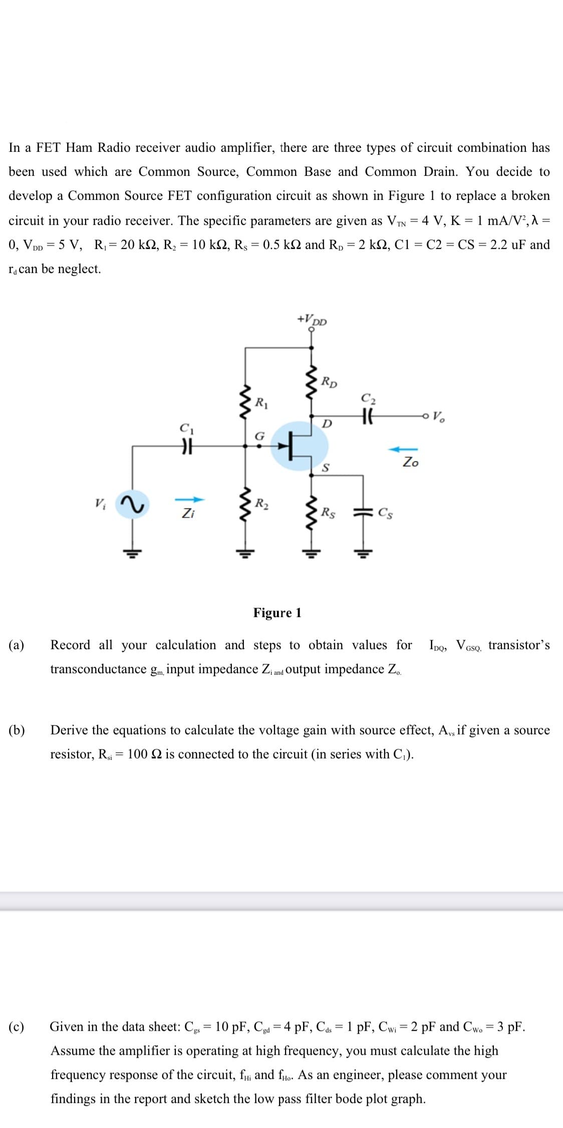
Transcribed Image Text:In a FET Ham Radio receiver audio amplifier, there are three types of circuit combination has
been used which are Common Source, Common Base and Common Drain. You decide to
develop a Common Source FET configuration circuit as shown in Figure 1 to replace a broken
circuit in your radio receiver. The specific parameters are given as VTN = 4 V, K = 1 mA/V²,A =
0, VDp = 5 V, R,= 20 k2, R, = 10 k2, Rs = 0.5 kN and Rp = 2 k2, C1 = C2 = CS = 2.2 uF and
ra can be neglect.
+VDD
Rp
C2
R1
HE
D
C1
G
Zo
R2
Zi
Rs
Figure 1
or
Ipo, VGso, transistor's
(a)
Record all your calculation and steps to obtain values
transconductance gm, input impedance Zi and Output impedance Z,.
(b)
Derive the equations to calculate the voltage gain with source effect, A, if given a source
resistor, R, = 100 2 is connected to the circuit (in series with C,).
(c)
Given in the data sheet: C, = 10 pF, Cd = 4 pF, Cas = 1 pF, Cwi = 2 pF and Cw. = 3 pF.
Assume the amplifier is operating at high frequency, you must calculate the high
frequency response of the circuit, fi and fuo. As an engineer, please comment your
findings in the report and sketch the low pass filter bode plot graph.
Expert Solution
This question has been solved!
Explore an expertly crafted, step-by-step solution for a thorough understanding of key concepts.

This is a popular solution!

Trending now
This is a popular solution!

Step by step
Solved in 4 steps with 4 images

Knowledge Booster


Learn more about
Need a deep-dive on the concept behind this application? Look no further. Learn more about this topic, electrical-engineering and related others by exploring similar questions and additional content below.Recommended textbooks for you
Introductory Circuit Analysis (13th Edition)
Electrical Engineering
ISBN:
9780133923605
Author:
Robert L. Boylestad
Publisher:
PEARSON

Delmar's Standard Textbook Of Electricity
Electrical Engineering
ISBN:
9781337900348
Author:
Stephen L. Herman
Publisher:
Cengage Learning

Programmable Logic Controllers
Electrical Engineering
ISBN:
9780073373843
Author:
Frank D. Petruzella
Publisher:
McGraw-Hill Education
Introductory Circuit Analysis (13th Edition)
Electrical Engineering
ISBN:
9780133923605
Author:
Robert L. Boylestad
Publisher:
PEARSON
Delmar's Standard Textbook Of Electricity
Electrical Engineering
ISBN:
9781337900348
Author:
Stephen L. Herman
Publisher:
Cengage Learning
Programmable Logic Controllers
Electrical Engineering
ISBN:
9780073373843
Author:
Frank D. Petruzella
Publisher:
McGraw-Hill Education

Fundamentals of Electric Circuits
Electrical Engineering
ISBN:
9780078028229
Author:
Charles K Alexander, Matthew Sadiku
Publisher:
McGraw-Hill Education

Electric Circuits. (11th Edition)
Electrical Engineering
ISBN:
9780134746968
Author:
James W. Nilsson, Susan Riedel
Publisher:
PEARSON

Engineering Electromagnetics
Electrical Engineering
ISBN:
9780078028151
Author:
Hayt, William H. (william Hart), Jr, BUCK, John A.
Publisher:
Mcgraw-hill Education,