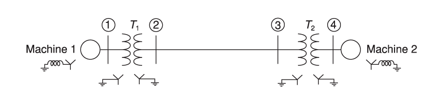
A single-line diagram of a four-bus system is shown in fiugre. Equipment ratings and per-unit reactances are given as follows. Machines 1 and 2: 100 MVA 20 kV; X1= X2 = 0.2; X0= 0.04 Xn= 0.05 Transformers T1 and T2: 100 MVA 20Y/345Y kV; X1 = X2 = X0 = 0.08. On a base of 100 MVA and 345 kV in the zone of the transmission line, the series reactances of the transmission line are X1 = X2 = 0.15 and X0=0.5 per unit. (a) Determine the bus impedance matrix for each of the three sequence networks. (b) Assume the system to be operating at nominal system voltage without prefault currents when a bolted single-line-toground fault occurs on phase A at bus 3. Compute the fault current, the current out of phase C of machine 2 during the fault, and the line-toground voltages at the terminals of machine 2 during the fault. Total detailed answer is needed. The figure is attached.


A single-line diagram of a four-bus system is shown in fiugre. Equipment ratings and per-unit reactances are given as follows.
Machines 1 and 2: 100 MVA 20 kV; X1= X2 = 0.2; X0= 0.04 Xn= 0.05 Transformers T1 and T2: 100 MVA 20Y/345Y kV; X1 = X2 = X0 = 0.08.
On a base of 100 MVA and 345 kV in the zone of the transmission line, the series reactances of the transmission line are X1 = X2 = 0.15 and X0=0.5 per unit.
(a) Determine the bus impedance matrix for each of the three sequence networks. (b) Assume the system to be operating at nominal system voltage without prefault currents when a bolted single-line-toground fault occurs on phase A at bus 3. Compute the fault current, the current out of phase C of machine 2 during the fault, and the line-toground voltages at the terminals of machine 2 during the fault. Total detailed answer is needed. The figure is attached.


Trending now
This is a popular solution!

Step by step
Solved in 3 steps with 4 images


