The positive-sequence reactances for the power system shown below are in per unit on a common MVA base. Resistances are neglected and the negative-sequence impedances are assumed to be the same as the positive-sequence impedances. The zero sequence reactances of each component in per-unit are given on the table below. 1. T1 1 2 T2 j0.6 X=j0.05 j0.15 j0.05 X=j0.05 G1 0.02 G2 0.02 3 j0.3 T1 0.15 T2 0.05 Obtain the Thevenin sequence impedances for the fault at bus 1 and compute the fault current in per unit for the following faults: L1(0.6) 0.80 L2(0.3) 0.50 A bolted three-phase fault at bus 1. A bolted single line-to-ground fault at bus 1. A bolted line-to-line fault at bus 1. a. b. C. A bolted double line-to-ground fault at bus 1. d.
The positive-sequence reactances for the power system shown below are in per unit on a common MVA base. Resistances are neglected and the negative-sequence impedances are assumed to be the same as the positive-sequence impedances. The zero sequence reactances of each component in per-unit are given on the table below. 1. T1 1 2 T2 j0.6 X=j0.05 j0.15 j0.05 X=j0.05 G1 0.02 G2 0.02 3 j0.3 T1 0.15 T2 0.05 Obtain the Thevenin sequence impedances for the fault at bus 1 and compute the fault current in per unit for the following faults: L1(0.6) 0.80 L2(0.3) 0.50 A bolted three-phase fault at bus 1. A bolted single line-to-ground fault at bus 1. A bolted line-to-line fault at bus 1. a. b. C. A bolted double line-to-ground fault at bus 1. d.

Power System Analysis and Design (MindTap Course List)
6th Edition
ISBN:9781305632134
Author:J. Duncan Glover, Thomas Overbye, Mulukutla S. Sarma
Publisher:J. Duncan Glover, Thomas Overbye, Mulukutla S. Sarma
Chapter3: Power Transformers
Section: Chapter Questions
Problem 3.29P: Consider three ideal single-phase transformers (with a voltage gain of ) put together as ...

Related questions
Question
I only need a solution for item (d)
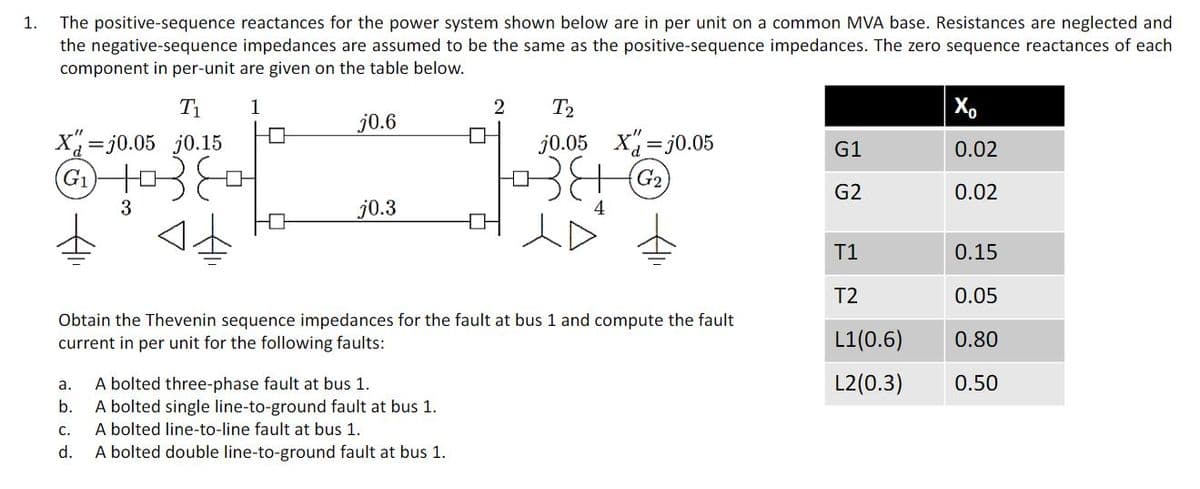
Transcribed Image Text:The positive-sequence reactances for the power system shown below are in per unit on a common MVA base. Resistances are neglected and
the negative-sequence impedances are assumed to be the same as the positive-sequence impedances. The zero sequence reactances of each
component in per-unit are given on the table below.
1.
T1
1
2
T2
X,
j0.6
X=j0.05 j0.15
j0.05 X=j0.05
G1
0.02
G2
G2
0.02
3
j0.3
4
T1
0.15
T2
0.05
Obtain the Thevenin sequence impedances for the fault at bus 1 and compute the fault
current in per unit for the following faults:
L1(0.6)
0.80
L2(0.3)
A bolted three-phase fault at bus 1.
A bolted single line-to-ground fault at bus 1.
A bolted line-to-line fault at bus 1.
A bolted double line-to-ground fault at bus 1.
a.
0.50
b.
C.
d.
Expert Solution
This question has been solved!
Explore an expertly crafted, step-by-step solution for a thorough understanding of key concepts.

This is a popular solution!

Trending now
This is a popular solution!

Step by step
Solved in 3 steps with 5 images

Recommended textbooks for you
Power System Analysis and Design (MindTap Course …
Electrical Engineering
ISBN:
9781305632134
Author:
J. Duncan Glover, Thomas Overbye, Mulukutla S. Sarma
Publisher:
Cengage Learning
Power System Analysis and Design (MindTap Course …
Electrical Engineering
ISBN:
9781305632134
Author:
J. Duncan Glover, Thomas Overbye, Mulukutla S. Sarma
Publisher:
Cengage Learning