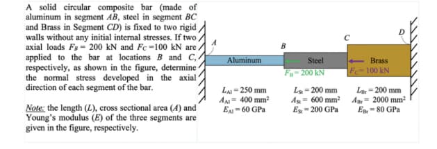
A solid circular composite bar (made of aluminum in segment AB, steel in segment BC and Brass in Segment CD) is fixed to two rigid walls without any initial internal stresses. If two axial loads Fs = 200 kN and Fc =100 kN are. applied to the bar at locations B and C,. respectively, as shown in the figure, determine the normal stress developed in the axial direction of each segment of the bar. Aluminum Steel Brass F-200 kN Fe=100 kN LAI = 250 mm A- 400 mm? E= 60 GPa Ls = 200 mm As = 600 mm A- 2000 mm Es - 200 GPa L = 200 mm Note: the length (L), cross sectional area (A) and Young's modulus (E) of the three segments are given in the figure, respectively. ER= 80 GPa
A solid circular composite bar (made of aluminum in segment AB, steel in segment BC and Brass in Segment CD) is fixed to two rigid walls without any initial internal stresses. If two axial loads Fs = 200 kN and Fc =100 kN are. applied to the bar at locations B and C,. respectively, as shown in the figure, determine the normal stress developed in the axial direction of each segment of the bar. Aluminum Steel Brass F-200 kN Fe=100 kN LAI = 250 mm A- 400 mm? E= 60 GPa Ls = 200 mm As = 600 mm A- 2000 mm Es - 200 GPa L = 200 mm Note: the length (L), cross sectional area (A) and Young's modulus (E) of the three segments are given in the figure, respectively. ER= 80 GPa

Mechanics of Materials (MindTap Course List)
9th Edition
ISBN:9781337093347
Author:Barry J. Goodno, James M. Gere
Publisher:Barry J. Goodno, James M. Gere
Chapter7: Analysis Of Stress And Strain
Section: Chapter Questions
Problem 7.2.2P: Solve the preceding problem for an element in plane stress on the bottom surface of a fuel tanker...

Related questions

Question
100%
HW problem help
Transcribed Image Text:A solid circular composite bar (made of
aluminum in segment AB, steel in segment BC
and Brass in Segment CD) is fixed to two rigid
walls without any initial internal stresses. If two
axial loads F3 = 200 kN and Fc =100 kN are .
applied to the bar at locations B and C,
respectively, as shown in the figure, determine-
the normal stress developed in the axial
direction of each segment of the bar.
Aluminum
Steel
Brass
F- 200 kN
Fe-100 kN
LA= 250 mm
A- 400 mm?
EA = 60 GPa
Ls = 200 mm
As = 600 mm? Am- 2000 mm2
Es = 200 GPa
La = 200 mm
Note: the length (L), cross sectional area (A) and
Young's modulus (E) of the three segments are
given in the figure, respectively.
E = 80 GPa
Expert Solution
This question has been solved!
Explore an expertly crafted, step-by-step solution for a thorough understanding of key concepts.

This is a popular solution!

Trending now
This is a popular solution!

Step by step
Solved in 3 steps with 3 images

Knowledge Booster


Learn more about
Need a deep-dive on the concept behind this application? Look no further. Learn more about this topic, mechanical-engineering and related others by exploring similar questions and additional content below.Recommended textbooks for you
Mechanics of Materials (MindTap Course List)
Mechanical Engineering
ISBN:
9781337093347
Author:
Barry J. Goodno, James M. Gere
Publisher:
Cengage Learning
Mechanics of Materials (MindTap Course List)
Mechanical Engineering
ISBN:
9781337093347
Author:
Barry J. Goodno, James M. Gere
Publisher:
Cengage Learning