A three-phase, half-wave uncontrolled rectifier is fed from an ideal three-phase voltage 50 Hz. The load is resistive with R=15 N. Calculate: (a) The average output voltage and average load current of the rectifier. (b) The d.c. and a.c. power dissipations in the load. (c) The diode ratings. (d) What is the lowest ripple frequency of the output voltage waveform? Pae,
A three-phase, half-wave uncontrolled rectifier is fed from an ideal three-phase voltage 50 Hz. The load is resistive with R=15 N. Calculate: (a) The average output voltage and average load current of the rectifier. (b) The d.c. and a.c. power dissipations in the load. (c) The diode ratings. (d) What is the lowest ripple frequency of the output voltage waveform? Pae,

Electricity for Refrigeration, Heating, and Air Conditioning (MindTap Course List)
10th Edition
ISBN:9781337399128
Author:Russell E. Smith
Publisher:Russell E. Smith
Chapter12: Electronic Control Devices
Section: Chapter Questions
Problem 4RQ: What is the difference between a diode and rectifier?

Related questions
Question
I need the answer quickly
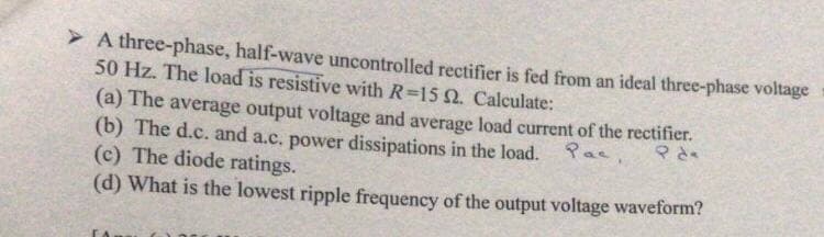
Transcribed Image Text:> A three-phase, half-wave uncontrolled rectifier is fed from an ideal three-phase voltage
50 Hz. The load is resistive with R=15 Q. Calculate:
(a) The average output voltage and average load current of the rectifier.
(b) The d.c. and a.c. power dissipations in the load. ae
(c) The diode ratings.
(d) What is the lowest ripple frequency of the output voltage waveform?
Expert Solution
This question has been solved!
Explore an expertly crafted, step-by-step solution for a thorough understanding of key concepts.

Step by step
Solved in 3 steps with 2 images

Knowledge Booster


Learn more about
Need a deep-dive on the concept behind this application? Look no further. Learn more about this topic, electrical-engineering and related others by exploring similar questions and additional content below.Recommended textbooks for you
Electricity for Refrigeration, Heating, and Air C…
Mechanical Engineering
ISBN:
9781337399128
Author:
Russell E. Smith
Publisher:
Cengage Learning
Electricity for Refrigeration, Heating, and Air C…
Mechanical Engineering
ISBN:
9781337399128
Author:
Russell E. Smith
Publisher:
Cengage Learning