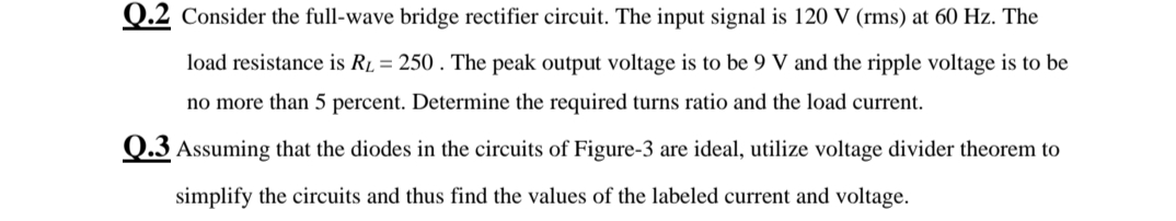
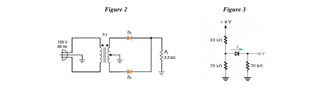
Q.2 Consider the full-wave bridge rectifier circuit. The input signal is 120 V (rms) at 60 Hz. The load resistance is RL = 250. The peak output voltage is to be 9 V and the ripple voltage is to be no more than 5 percent. Determine the required turns ratio and the load current. Q.3 Assuming that the diodes in the circuits of Figure-3 are ideal, utilize voltage divider theorem to simplify the circuits and thus find the values of the labeled current and voltage.
Q.2 Consider the full-wave bridge rectifier circuit. The input signal is 120 V (rms) at 60 Hz. The load resistance is RL = 250. The peak output voltage is to be 9 V and the ripple voltage is to be no more than 5 percent. Determine the required turns ratio and the load current. Q.3 Assuming that the diodes in the circuits of Figure-3 are ideal, utilize voltage divider theorem to simplify the circuits and thus find the values of the labeled current and voltage.

Chapter59: Motor Startup And Troubleshooting Basics
Section: Chapter Questions
Problem 12SQ: How is a solid-state diode tested? Explain.

Related questions
Question
Transcribed Image Text:Q.2 Consider the full-wave bridge rectifier circuit. The input signal is 120 V (rms) at 60 Hz. The
load resistance is R1 = 250 . The peak output voltage is to be 9 V and the ripple voltage is to be
no more than 5 percent. Determine the required turns ratio and the load current.
Q.3 Assuming that the diodes in the circuits of Figure-3 are ideal, utilize voltage divider theorem to
simplify the circuits and thus find the values of the labeled current and voltage.
Transcribed Image Text:Figure 2
Figure 3
+ 6 V
D1
7:1
10 kn
120 V
60 Hz
>3.3 ka
20 kn 3
20 kn
D2
Expert Solution
This question has been solved!
Explore an expertly crafted, step-by-step solution for a thorough understanding of key concepts.

Step by step
Solved in 2 steps

Knowledge Booster


Learn more about
Need a deep-dive on the concept behind this application? Look no further. Learn more about this topic, electrical-engineering and related others by exploring similar questions and additional content below.Recommended textbooks for you

Electricity for Refrigeration, Heating, and Air C…
Mechanical Engineering
ISBN:
9781337399128
Author:
Russell E. Smith
Publisher:
Cengage Learning
Electricity for Refrigeration, Heating, and Air C…
Mechanical Engineering
ISBN:
9781337399128
Author:
Russell E. Smith
Publisher:
Cengage Learning