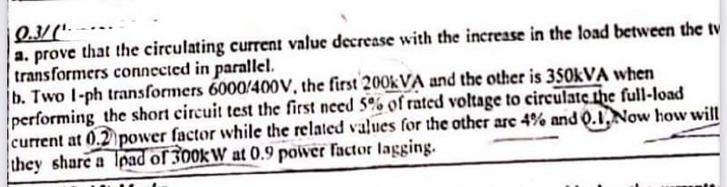
a. prove that the circulating current value decrease with the increase in the load between the tv transformers connected in parallel. formers 6000/400V, the first 200kVA and the other is 350kVA when
Q: How can you determine the polarity of a light-emitting diode? And at what circumstances does a…
A: A diode is a two terminal semiconductor electronic device. The diode is made up of semiconductor…
Q: How is a current of 10A shared by three circuits in parallel, the impedance of which are 2-j5),…
A:
Q: B/ Find the (BCD) for the decimal number (71536) when the code is :- 1- code (9,- 4, 3, -2) 2- code…
A: Given here a decimal number and asked to find its representation in BCD code when different codes…
Q: Q2: For the circuit of fig.(3), the voltage and current sources are given in a form of Fourier…
A: The circuit diagram is shown below, Where,Vt=50+40 sinωt+30 sin3ωt+25 sin5ωt+30…
Q: 1. Calculate the power gain in decibels for each of the following cases. a. Po 100 W, P₁ = 5 W.
A: Given, Output power, Po=100 W Input power, Pi=5 W
Q: Example 13.2. A 2-wire d.c. distributor AB is 300 metres long. It is fed at point A. The various…
A:
Q: Q5. Calculate the maximum and minimum collector current in (fig. 6) and find Icsat. and VCEsat. Vcc…
A:
Q: V2 1+ R3 ww W 12 R1 Let R1 6 ohm, R2 = 5 ohm, R3 = 14 ohm, V2 = 14 volt, 11 = 1 ampere and 12 = 4…
A:
Q: +CC W1 +PC 6V 3A 15V + PC- +CC W2 Wattmeter W1 reads 75 W Wattmeter W2 reads 60 Determine the total…
A: Two wattmeter method is used to find balanced or unbalanced three phase three wire circuits Three…
Q: Given an input energy from sunlight of 1000 kWh, solar panels can generate about 170 kWh of…
A: The efficiency of the solar panel is, ηsolar=PoutPinPout=170 kWhPin=1000…
Q: c) For the circiut shown in fig.(2), the swit find ix(t) for t>0, let R₁ R₂=1k2, R3-2k2, a. Fig.(2)
A: In this question we will find current through resistor R1 ....
Q: If, in a 3-4 alternator, a field current of 50 A produces a full-load armature current of 200 A on…
A: Given, A 3-φ alternator has, Field current of 50 A Open circuit line voltage, Vocline=1730 V Open…
Q: QUESTION 14 The diagram shows an electromagnet electric pell. Describe how the bell on the right…
A: When the switch is closed, the electromagnet magnetizes and attracts the soft iron armature of the…
Q: A common emitter class A transistor power amplifier uses a transistor with B=100. The load has a…
A:
Q: Bandwidth occupied by 100 MHz carrier; AM modulated by signal frequency of 10 kHz is?
A: Given, Carrier frequency, fc=100 MHz Modulating frequency, fm=10 kHz
Q: Q1) A- Two signals x₁(t) and x₂ (t) having Fourier transforms X₁(f) and X₂(f)shown in figure (1) are…
A: The spectrum of signal x1(t) is given as And, The spectrum of signal x2(t) is given as
Q: fa A 3-phase ring main ABCD fed at A at 11 kV supplies balanced loads of 50 A at 0.8 p.f. lagging at…
A: Below figure shows one phase of the ring main. The problem gets solved by Kirchhoff'slaw. Let…
Q: Find ix and the power developed in the dependent current source, 2vx-
A: In the given circuit, we have to find ix and power developed in dependent current source 2Vx.
Q: 4.4 A boost-regulator has an input voltage of 5 the average output voltage of 15 V. The duty cycle…
A: Given a boost regulator has, Input voltage, Vin=5 V Average output voltage, Vo=15 V
Q: sisting of a coil of inductance 0.1 H and resistance 8ohms and a capacitor of 120uF nected to a…
A:
Q: 3- (A)16 4- By Boolean Algebra YZ + (X + Z) + (XY+XZ) = Z + X. 5- OR gate produce 1 out puts when…
A: According to bartleby question answer rule I have to solve one question because all are different…
Q: a=2 A 4-pole, 25 kw, 250V, wave-wound shunt generator has 361 armature turns, brush leads by 8…
A: In this question we will find shunt generator armature demagnetizing and cross magnetizing ampere…
Q: Let G(s) = -K(s + 1)² s² +2s +2 with K > 0 in Figure P8.3. [Sections: 8.5, 8.9] a. Find the range of…
A: Given G(s)=-Ks+12s2+2s+2 with K>0. a. We need to find the range of K for closed-loop stability.…
Q: Please I want a table of comparisons between plc & Dcs & scada
A: Comparison between PLC, Dcs and Scada, PLC…
Q: The circuit shown in Figure Q3 has a DC source. For time t<0 Vin has been at 01 V DC for a long…
A: Since you have asked multiple questions in a single request, we will be answering only the first…
Q: The current flowing through a heating element is 5 A when a p.d. of 35 V is applied across it. Find…
A: Given, The current flowing through a heating element, I=5 A Potential difference across this, V=35 V
Q: R + CC PC + W₁ +CC IR N 21 ly Z₂ 23 PC + W₂ 1B B. Supply voltage = 400V (line-to-line), phase…
A: Types of power measurement Three wattmeter method Two wattmeter method One wattmeter method
Q: Q/ derive Ri High Pass Filter? R₂
A: Given data, Circuit diagram is given as,
Q: What will be the magnetic susceptibility of a material kept in free space if the field strength of…
A: Given: Magnetic field intensity, H=0.4×10⁷ Am Magnetic flux density, B=12 T
Q: Q4. In a CE germanium transistor amplifier circuit shown in (fig. 5). Determine the 0.985. operating…
A: We will find out the Q point of given circuit and load line
Q: Where are cable operator signals the most weakest and distorted? (Choose 2) at the photodiode…
A: Since you have posted multiple MCQ-type questions, we will solve the first three questions for you.…
Q: Find V₂ (t) for all time t.
A: It is given that:
Q: -A 6-pole, wave-wound a long-shunt compound generator delivers a load current of 50 A at 500V and…
A:
Q: find the shaft (output) torque. a
A: The motor converts electrical energy into mechanical energy. The output torque of series motor…
Q: Q2: For the circuit of fig.(3), the voltage and current sources are given in a form of Fourier…
A: A closed path, where electric current can flow defined as an electric circuit. It is various…
Q: In the below given figure, two capacitances are in series with a 18V source. The capacitance of the…
A:
Q: Problem 2 Find VR (t) for all time t. 4 V 202 HI st=0 t=0 2 H + VR 222 Ω
A: In this question, We need to determine the voltage across the resistance R as shown the circuit.…
Q: For the figure shown below, the permeability in the core is 4 x 10 Wb/A-tums-m. What is the value of…
A:
Q: Ex: G(s) = solution S+ 3 S+50 Analytical method bode plot
A: In the analytic approach there is no need to plot the bode plot on the semilog graph. For the given…
Q: Balanced 3 Phase Supply CC PC S B A NB N The 3-phase load consumes a totál power of 42 kW at 0.4…
A:
Q: Balanced 3 Phase Supply A CC PC S BCN A 90 Balanced 3 Phase Load IN B The 3-phase load consumes a…
A: Methods of power measurement in three phase circuit One wattmeter method Two wattmeter method…
Q: A broadcast AM transmitter radiates 50 KW of carrier power. The radiation power at 85 % of…
A: Given: A broadcast AM transmitter radiates, Carrier power, Pc=50 kW Modulation factor, μ=85 %=0.85
Q: For the series circuit in Figure 3. Determine the total impedance Z₁ expressed in Rectangular form.…
A:
Q: Problem 18. The standing-wave ratio on a mis- matched line is calculated as 1.60. If the incident…
A: Given, Standing wave ratio, s = 1.60 Incident power arriving at the transmission, Pt=200 mW…
Q: : Answer briefly: 1. A certain BJT amplifier exhibits three critical frequencies in its low…
A: We are authorized to answer three sub-parts at a time, since you have not mentioned which part you…
Q: 2 for the resonate at all frequencies. www R2 4 mB LOMF7 * below which will make the cir
A:
Q: RF carrier 10 KV at 1 MHz is amplitude modulated and modulation index is 0.6. Peak voltage of the…
A:
Q: 21): For the circuit shown in fig.(1), t and then at time (t-0), the switch is m method, find ir(t),…
A: Given: The switch is at position 1 for a long period of time in the below-given figure.
Q: Q5-B- Realize the function F= A + BCD by basic gates and write the truth table?
A: We will draw logic diagram and truth table
Q: Impedances z₂ and z3 in parallel are in series with an impedance z₁ across a 100V,50Hz AC supply. Z₁…
A: For the above given question we need to calculate the value of current, power and XC at resonance.
Step by step
Solved in 2 steps with 2 images
- Three single-phase two-winding transformers, each rated 25MVA,34.5/13.8kV, are connected to form a three-phase bank. Balanced positive-suence voltages are applied to the high-voltage terminals, and a balanced, resistive Y load connected to the low-voltage terminals absorbs 75 MW at 13.8 kV. If one of the single-phase transformers is removed (resulting in an open connection) and the balanced load is simultaneously reduced to 43.3 MW (57.7 of the original value), determine (a) the load voltages Va,Vb, and Vc; (b) load currents Ia,Ib, and Ic; and (c) the MVA supplied by each of the remaining two transformers. Are balanced voltages still applied to the load? Is the open transformer overloaded?Consider two interconnected voltage sources connected by a line of impedance Z=jX, as shown in Figure 2.27. (a) Obtain expressions for P12 and Q12. (b) Determine the maximum power transfer and the condition for it toIn developing per-unit equivalent circuits for three-phase transformers. under balanced three-phase operation. (i) A common Sbase is selected for both the H and X terminals. (ii) The ratio of the voltage bases Vbase/VbaseX is selected to be equal to the ratio of the rated line-to-line voltages VratedHLL/VratedXLL. (a) Only one of the above is true. (b) Neither is true. (C) Both statements are true.
- With generator conyention, where the current leaves the positive terminal of the circuit element, if P is positive then positive real power is delivered. (a) False (b) TrueConsider a single-phase electric system shown in Figure 3.33. Transformers are rated as follows: XY15MVA,13.8/138kV, leakage reactance 10 YZ15MVA,138/69kV, leakage reactance 8 With the base in circuit Y chosen as 15MVA,138kV determine the per-unit impedance of the 500 resistive load in circuit Z, referred to circuits Z, Y, and X. Neglecting magnetizing currents, transformer resistances, and line impedances, draw the impedance diagram in per unit.A single-phase 100-kVA,2400/240-volt,60-Hz distribution transformer is used as a step-down transformer. The load, which is connected to the 240-volt secondary winding, absorbs 60 kVA at 0.8 power factor lagging and is at 230 volts. Assuming an ideal transformer, calculate the following: (a) primary voltage, (b) load impedance, (c) load impedance referred to the primary, and (d) the real and reactive power supplied to the primary winding.
- PowerWorid Simulator case Problem 3_60 duplicates Example 3.13 except that a resistance term of 0.06 per unit has been added to the transformer and 0.05 per unit to the transmission line. Since the system is no longer lossless, a field showing the real power losses has also been added to the oneline. With the LTC tap fixed at 1.05, plot the real power losses as the phase shift angle is varied from 10 to +10 degrees. What value of phase shift minimizes the system losses?An infinite bus, which is a constant voltage source, is connected to the primary of the three-winding transformer of Problem 3.53. A 7.5-MVA,13.2-kV synchronous motor with a sub transient reactance of 0.2 per unit is connected to the transformer secondary. A5-MW,2.3-kV three-phase resistive load is connected to the tertiary Choosing a base of 66 kV and 15 MVA in the primary, draw the impedance diagram of the system showing per-unit impedances. Neglect transformer exciting current, phase shifts, and all resistances except the resistive load.A balanced three-phase load is connected to a 4.16-kV, three-phase, fourwire, grounded-wye dedicated distribution feeder. The load can be mode led by an impedance of ZL=(4.7+j9)/phase, wye-connected. The impedance of the phase conductors is (0.3+j1). Determine the following by using the phase A to neutral voltage as a reference and assume positive phase sequence: (a) Line currents for phases A, B, and C. (b) Line-to-neutral voltages for all three phases at the load. (c) Apparent. active, and reactive power dissipated per phase, and for all three phases in the load. (d) Active power losses per phase and for all three phases in the phase conductors.
- A Y-connected load bank with a three-phase rating of 500 kVA and 2300 V consists of three identical resistors of 10.58. The load bank has the following applied voltages: Vab=184082.8,Vbc=276041.4, and Vca=2300180V. Determine the symmetrical components of (a) the line-to-line voltages Vab0,Vab1, and Vab2, (b) the line-to-neutral voltages and Van0,Van1, and Van2, (c) and the line currents Ia0,Ia1, and Ia2. (Note that the absence of a neutral connection means that zero-sequence currents are not present.)While the instantaneous electric power delivered by a single-phase generator under balanced steady-state conditions is a function of time havi ng two components of a constant and a double-frequency sinusoid, the total instantaneous electric power delivered by a three-phase generator under balanced steady-state conditions is a constant. (a) True (b) FalseA single-phase, 120V(rms),60Hz source supplies power to a series R-L circuit consisting of R=10 and L=40mH. (a) Determine the power factor of the circuit and state whether it is lagging or leading. (b) Determine the real and reactive power absorbed by the load. (c) Calculate the peak magnetic energy Wint stored in the inductor by using the expression Wint=L(Irms)2 and check whether the reactive power Q=Wint is satisfied. (Note: The instantaneous magnetic energy storage fluctuates between zero and the peak energy. This energy must be sent twice each cycle to the load from the source by means of reactive power flows.)