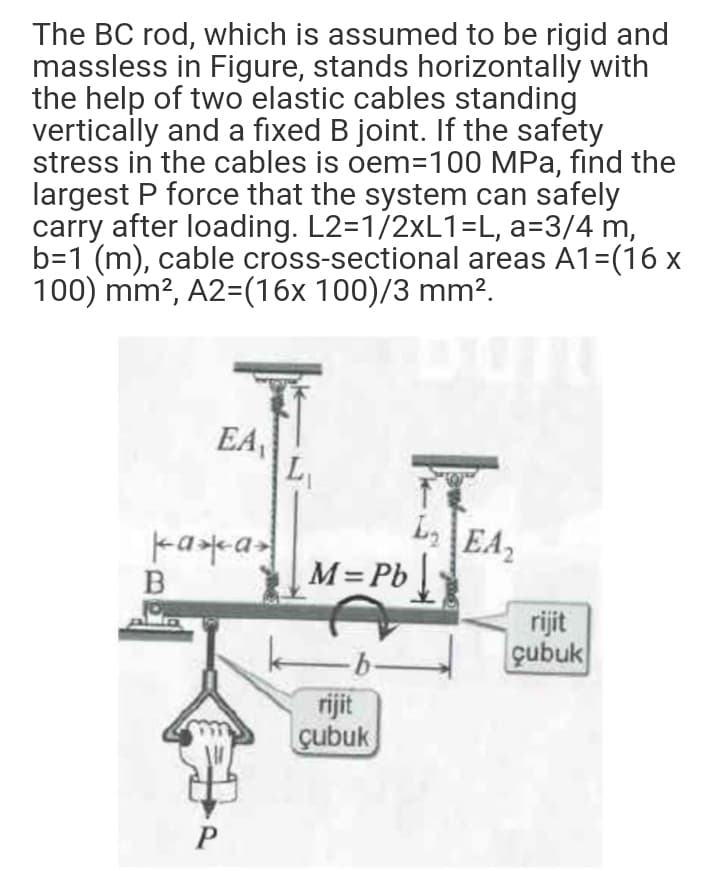
The BC rod, which is assumed to be rigid and massless in Figure, stands horizontally with the help of two elastic cables standing vertically and a fixed B joint. If the safety stress in the cables is oem=100 MPa, find the largest P force that the system can safely carry after loading. L2=1/2×L1=L, a=3/4 m, b=1 (m), cable cross-sectional areas A1=(16 x 100) mm?, A2=(16x 100)/3 mm².
Q: Figure Q2 shows a rigid link supported by a pin at C and two A-36 steel wires. Each wire having an…
A:
Q: wo flat bars loaded in tension by force P are spliced with the use of two rectangular splice plates…
A: Given Data: The diameter of the bolts is d =0.375 in. The width of the bar is b = 0.625 in and…
Q: *2.5-11 A rigid triangular frame is pivoted at C and held by two identical horizontal wires at…
A: Given, EA=120 klb=120×103 lb α=12.5×10⁻⁶ /0F
Q: Consider the frame shown in Fig 4. A 100N load is suspended around a fixed drum with radius 2 m…
A:
Q: A rectangular polypropylene [E = 6,200 MPa] bar (1) is connected to a rectangular nylon [ E = 1,400…
A: GIVEN DATA- Two bar connected at flange B For bar 1 A1=990mm2 , L1=1600mm , E1=6200MPa For bar 2…
Q: 2. Link BE and cable CF are attached to a pin on one end and a rigid bar ABCD at the other end. Both…
A:
Q: Consider the frame shown in Fig 4. A 100N load is suspended around a fixed drum with radius 2 m…
A:
Q: AB, BC, BD ropes made of material with elasticity value in Table 2 are in balance as shown in the…
A: Given Data: θ=90° β=120° α=150° FAB=40000 N Areas: AAB=200 mm2 ABC=173 mm2 ABD=100 mm2 Lengths:…
Q: Axial loads are applied with rigid bearing plates to the solid cylindrical rods shown in the figure.…
A: Diameter of each section can be calculated by calculating net force on each section . 1. Calculate…
Q: Q-4 The polymer bar shown in Figure Q-4 has a width b = 50 mm, a depth d= 100 mm, and a height h=…
A:
Q: a) Figure Q4 (a) shows an L-bracket ABC with diameter d which lies in the horizontal plane. It is…
A:
Q: Q3) A short stepped bar is shown in Figure below. The stiffness of the large section is 12 kN/mm and…
A: Given data: k1=12 kN/mmk2=8 kN/mmF=6 kN Need to determine the displacement of the nodes 2 and 3.
Q: The figure below is a schematic drawing of a shaft that supports two V-belt pulleys. The loose belt…
A: Given, The yield strength of the material, sy=300 MPa The ultimate strength of the material, su=520…
Q: TYPE B • Example: 1 A rigid bar AB, 9 m long, is supported by two vertical rods at its end and in a…
A: To obtain the solution to the above question, we must use the three equation of statics which are-…
Q: An angle bracket having a thickness t=0.75 in. is attached to the flange of a column by two 5/8-inch…
A: Given data, Thickness of the bracket, t = 0.75 in Diameter of the bolt, db = 0.625 in Pressure on…
Q: ON 3 A brass rod AD (see figure) has a cross-sectional area of A- 250 mm' and is loaded by forces P…
A: Given: Cross sectional area of the rod AD is A=250 mm2 and forces acting are P1=15 KN, P2=10 KN and…
Q: Q2 A rigid triangular frame is pivoted at C and held by two identical horizontal wires at points A…
A: givenforce acting on triangular frame P=500lbaxial rigidity EA=120ksithermal expansion…
Q: A cable and pulley system in the figure parta supports a cage of a mass 300 kg at B. Assume thatthis…
A: Given that, Total mass at B, m=300 kg,Thickness of each pulley, t=40 mm,Diameter of the pin at A,…
Q: Q3/ A truss shown in Figure below is made of Aluminium and it consists of two rods. The…
A:
Q: (a) The column shown in Figure Q3 below is constructed from high-strength concrete and six steel…
A:
Q: 2.4-1 The assembly shown in the figure consists of a brass core (diameter d, = 0.25 in.) surrounded…
A: given data:-diameter of brass, d1=0.25in=0.00635m⇒Cross-sectional area of brass,…
Q: In the figure, one end of a uniform beam of weight 440 N is hinged to a wall; the other end is…
A: Consider the FBD as shown below.
Q: The steel plane truss shown in the figure is loaded by three forces P, each of which is 490 KN. The…
A: a) To find : The reaction at joint A and B and force in member AB , BC ,and AB Given : The Area…
Q: Three uniform cross-section rods, two of material A and one of material B, transmit the tensile…
A:
Q: A uniform steel bar of length 10 m is supported at point A and B using two cables as shown in the…
A:
Q: A rectangular column with cross-sectional dimensions b and h is pin-supported at ends A and C (see…
A: Draw the diagram of the cross-section X-X. Here, the axes x-x and y-y are as shown in the figure.…
Q: Axial loads are applied with rigid bearing plates to the solid cylindrical rods shown in the figure.…
A:
Q: 1.2-10 A car having a mass of 5500 kg is pulled slowly up a steep inclined track by a steel cable…
A:
Q: PROBLEMS Figure 1. In the figure shown, a bar ABC with negligible mass carries a 20 kN load and is…
A: Draw FBD
Q: A plane frame with pin supports at A and Ehas a cable attached at C, which runs over a…
A: a.Free body diagram: No horizontal force on frame,henceEx=0Now,Ey+Ay=500lb⇒Ey=500lb-AyNow,Net…
Q: The system in the figure is carried by a 50 mm diameter column. If the modulus of elasticity of the…
A: Given, The diameter of column, d = 50 mm Modulus of elasticity, E = 70 GPa The length of column, L =…
Q: 1.10-10 A cable and pulley system at D is used to bring a 230-kg pole (ACB) to a vertical position,…
A:
Q: 2.4-23 A trimetallic bar is uniformly compressed by an axial force P = 9 kips applied through a…
A:
Q: In the figure, one end of a uniform beam of weight 130 N is hinged to a wall; the other end is…
A:
Q: A bar, AB, with length L = 2 m and with weight Wand is held by two springs (see figure 1.1). The…
A: Calculated the distance x ,where force p is applied ,bar become in horizontal ,when the unstressed…
Q: In the figure, one end of a uniform beam of weight 130 N is hinged to a wall; the other end is…
A: To find: The tension in the wire. Given: The weight of the one end of the beam is hinged to the wall…
Q: *2.5-11 A rigid triangular frame is pivoted at C and held by two identical horizontal wires at…
A:
Q: A rigid bar ABCD is pinned at point B and supported by springs at A and D see figure. The springs at…
A:
Q: A cable and pulley system at D is used tobring a 230-kg pole (ACB) to a vertical position, asshown…
A: Draw a diagram for the problem. Here, W is the weight of the pole, T is the tension in the cable,…
Q: The homogeneous bar shown in Fig. P-106 is supported by a smooth pin at C and a cable that runs from…
A:
Q: Consider the truss as shown in the figure and parameter table. The maximum allowable tensile force…
A:
Q: AB rigid bar in the figure, P force acts at point B, which is articulated at point A.…
A: Given that, A1=8 cm2A2=4 cm2E1=E2=E=10 kN/cm2L=100 cm,P=13 kN, Drawing the reaction force in the…
Q: n the figure, torsional moments act on a bar system of abruptly changing cross-section made of the…
A:
Q: A rectangular column with cross-sectional dimensions b and h is pin-supported at ends A and C (see…
A: Let, E = Young’s modulus of column I = moment of inertia Drawing the two principal planes of the…
Q: support reaction forces
A: Given: A plane frame with load 2P as shown in Fig To determine all support reaction Forces
Q: The pin-ended wrought-iron pipe shown in the figure below has outer diameter D, inside diameter d,…
A: Given:-D=190mmd=170mmL=3.5mP=430 kNE=190 GPan=1.4σy=210 MPaTo find:-Largest allowable eccentricity
Q: The vertical rectanguler cross section column shown in Fig. Q4 is pinned at both ends. Assuming the…
A:
Q: In the system in the figure, two rods carry the P force. a) Since the maximum stress that the rods…
A:
Q: The pin-connected structure shown in the figure consists of a rigid beam ABCD and two supporting…
A: (a) Draw a free-body diagram of the beam.
Q: QUESTION 3 A steel bar AD has a cross-sectional area of 260 mm² is illustrated in Figure Q3. The…
A:
Step by step
Solved in 8 steps with 11 images
- Two separate cables AC and BC support a sign structure of weight W = 1575 lb attached to a building. The sign is also supported by a pin support at O and a lateral restraint in the '-direction at D. (a) Find the tension in each cable. Neglect the mass of the cables. (b) Find the average stress in each cable if the area of each cable is Ae= 0.471 in2.A 150-lb rigid bar AB. with friction less rollers al each end. is held in the position shown in the figure by a continuous cable CAD. The cable is pinned at C and D and runs over a pulley at A. (a) Find reactions at supports A and B. (b) Find the force in the cable.By what distance h does the cage shown in the figure move downward when the weight W is placed inside it? (See the figure.) Consider only the effects of the stretching of the cable, which has axial rigidity EA = 10,700 kN. The pulley at A has a diameter da= 300 mm and the pulley at B has a diameter dB= 150 mm. Also, the distance L1= 4.6 m, the distance L2=10.5 m, and the weight W = 22 kN. Note: When calculating the length of the cable. include the parts of the cable that go around the pulley sat A and B.
- A rigid bar of weight W = SOO N hangs from three equally spaced vertical wines( length L = 150 mm, spacing a = 50 mm J: two of steel and one of aluminum. The wires also support a load P acting on the bar. The diameter of the steel wires is ds= 2 mm, and the diameter of the aluminum wire is d = A mm. a Assume £,=210 GPa and EB« 70 GPa. What load Pallowcan be supported at the mitl-point of the bar (x = a) if the allowable stress in the steel wires is 220 MPa and in the aluminum wire is 80 MPa? (See figure part (b) What is /*,Ikw» if the load is positioned at .v = all1? (See figure part a.) (c) Repeat part (b) if the second and third wires are switched as shown in the figure part b.A hollow circular pipe (see figure} support s a load P that is uniformly distributed around a cap plate at the top of the lower pipe. The inner and outer diameters of the upper and lower parts of the pipe are d1= 50 mm, d2= 60 mm, rf3 = 57 mm, and d1= 64 mm, respectively. Pipe lengths are Lt= 2 m and L, = 3 m. Neglect the self-weight of the pipes. Assume that cap plate thickness is small compared to I, and E,. Let E = 110 MPa. (a) If the tensile stress in the upper part is d = 10.5 MPa. what is load PI Also, what are reactions ft, at the upper support and R-, at the lower support? What is the stress ar(MPa) in the lower part? (b) Find displacement S(mm) at the cap plate. Plot the axial force diagram (AFD) [Ar(.f)] and axial displacement diagram (ADD)[5(.t)]. (c) Add the uniformly distributed load q along the censorial axis of pipe segment 2. Find q (kN/m) so that It, = 0. Assume that load P from part (a) is also applied.A uniform bar AB of weight W = 25 N is supported by two springs, as shown in the figure. The spring on the left has a stiffness k[= 300 N/m and natural length Lt=250 mm. The corresponding quantities for the spring on the right are k2= 400 N/m and L^ = 200 mm. The distance between the springs is L = 350 mm, and the spring on the right is suspended from a support that is a distance it = SO mm below the point of support for the spring on the left. Neglect the weight of the springs. (a) At what distance x from the left-hand spring (figure part a) should a load P = 18 N be placed in order to bring the bar to a horizontal position? (b) If P is now removed, what new value of k{is required so that the bar (figure part a) will hang in a horizontal position underweight If? (c) If P is removed and kt= 300 N/m. what distance b should spring ktbe moved to the right so that the bar (figure part a) will hang in a horizontal position under weight II"? (d) If the spring on the left is now replaced by two springs in series (kt= 300 N/m, kt) with overall natural length Lt= 250 mm (see figure part b). what value of k; is required so that the bar will hang in a horizontal position under weight IF?
- Solve the preceding problem if the mass of the tailgate is MT— 11 kg and that of the crate is hic— 6S kg. Use dimensions H = 305 mm, L = 406 mm, dc= 460 mm, and dT= 350 mm. The cable cross-sectional area is At= 11.0 mm'. (a) Find the tensile Force T and normal stress T in each cable. (b) IF each cable elongatesA framework ABC consists of two rigid bars AB and BC. Each having a length b (see the first part of the figure part a). The bars have pin connections at A, B, and C and are joined by a spring of stiffness k. The spring is attached at the midpoints of the bars. The framework has a pin support at A and a roller support al C, and the bars are at an angle a to the horizontal. When a vertical load P is applied at joint B (see the second part of the figure part a.) the roller support C moves to the right, the spring is stretched, and the angle of the bars decreases from a to the angle ??. (a) Determine the angle 0 and the increase S in the distance between points A and C. Also find reactions at A and C. (Use the following data: b = 200 mm. ft = 3.2 kN/m. a = 45°. and P = 50 N.) (b) Repeat part (a) if a translational spring kt= kll is added at C and a rotational spring kr= kb-l2 is added at A (see figure pan b).A plane frame with a pin support at A and roller supports at C and £ has a cable attached at E. which runs over Frictionless pulleys al D and B (see figure). The cable force is known to be 400 N. There is a pin connection just Lo the left of joint C. (a) Find reactions at supports^, C, and E. (b) Find internal stress, resultants N, V, and M just to the right of joint C. (c) Find resultant force in the pin near C.
- A long, slender bar in the shape of a right circular cone with length L and base diameter d hangs vertically under the action of its own weight (see figure). The weight of the cone is W and the modulus of elasticity of the material is E. Derive a formula for the increase S in the length of the bar due to its own weight. (Assume that the angle of taper of the cone is small.)A soccer goal is subjected to gravity loads (in the - z direction, w = 73 N/m for DG, BG, and BC; w = 29 N/m for all other members; see figure) and a force F = 200 N applied eccentrically at the mid-height of member DG. Find reactions at sup ports C, D, and H.Space frame A BCD is clamped at A, except it is Free to translate in the .v direction. There is also a roller support at D, which is normal to line CDE. A triangularly distributed Force with peak intensity q0 = 75 N/m acts along AB in the positive - direction. Forces Px= 60 N and Pz = = 45 N are applied at joint C, and a concentrated moment My = 120 N . m acts at the mid-span of member BC. (a) Find reactions at supports A and I). (b) Find internal stress resultants N. E’I T, and .11 at the mid-height of segment AB.