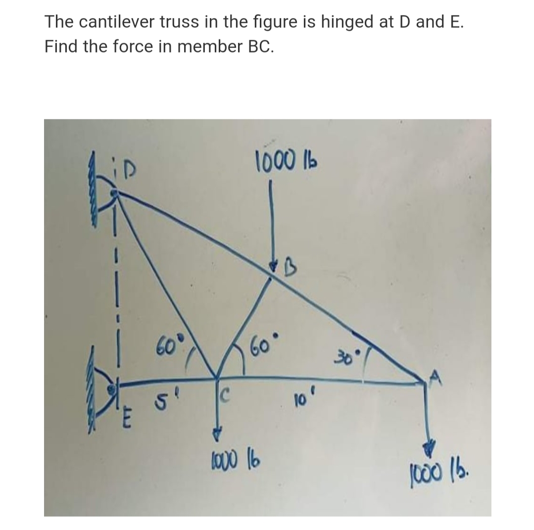
The cantilever truss in the figure is hinged at D and E. Find the force in member BC. 1000 1b 60 60° 30° C lo' lo00 16


Q: All the tension/compression members of the frame structure shown in the figure are pin-jointed and…
A:
Q: The cantilever truss in the figure is hinged at D and E. Find the force in member AC. 1000 Ib 60 60•…
A:
Q: Assume the plate shown in Figure has negligible weight. There is a ball and socket joint at A and a…
A:
Q: W.S. 2.50 m A 1.50 m B
A:
Q: The system with two pin supports, and having an internal pin at C, is subject to two horizontal…
A:
Q: In the figure, one end of a uniform beam of weight 480 N is hinged to a wall; the other end is…
A:
Q: Q. 60. The figure shows a schematic layout of a hydraulic jack. The load to be raised weighs 20,000…
A:
Q: Given: Truss ABCD below. P1 = 57 kN P2 = 33 kN Find: The magnitude of the force in each member and…
A:
Q: The vertical structure ABCD shown in Figure 1(a) is subjected to a system of coplanar forces and a…
A:
Q: The cantilever truss in the figure is hinged at D and E. Find the force in member BD. 1000 1b 60 60…
A:
Q: In the figure, one end of a uniform beam of weight 410 N is hinged to a wall; the other end is…
A: ...
Q: 4) Use the method of members to find the true magnitude and direction of the forces in the members…
A:
Q: Find the forces in members CE and CF in the figure below using the method of sections. Enter your…
A:
Q: Two steel ropes connected to each other at point C are loaded as shown in the figure. The maximum…
A:
Q: METHOD OF JOINTS * The Cantilever truss in figure below is hinged at D and E. Find the force in each…
A: The forces in each member of the truss are: ◆ FAB = 2000 lb ...(Tension) ◆ FAC = -1732.05 lb…
Q: A force of 100 lb is applied to the frame shown (See the Figure below). Calculate the load in member…
A:
Q: Consider the truss shown with a 125-lb load on point B. What is the magnitude and direction of the…
A: The magnitude and direction of the roller support on point E.
Q: B 芝 9 KN 5m 3 m 3 m 60° In the figure shown, connections at A, B, and C are pin joints. a) Draw the…
A:
Q: Question 2: The cross-sectional area for the lattice rods in the figure is A=120 mm2, the modulus of…
A: Solution
Q: The cantilever truss in the figure is hinged at D and E. Find the force in member CE. 1000 Ib 60 60°…
A:
Q: The plate shown in (Figure is supported by a roller and a cable in the x-direction at A, a…
A: Given: The dimension of side AB is L=1.5 m. The dimension of side BC is L=1.5 m. The force applied…
Q: The assembly in Figure below consists of a light rigid bar AB, pinned at O, that is attached to the…
A: Given:AB=0.75mOB=1.5m∆=5mmFor steelAst=250mm2E=200 GPaFor aluminiumL=BC=2mAal=300mm2E=70 GPaTo find…
Q: Given: Truss ABCD below. P1 = 57 kN P2 = 33 kN Find: The magnitude of the force in each member and…
A: Given P1=57KN P2=33kn
Q: A plane truss is shown in the figure. a = 4 m, b = 13 m, F = 18 kN. F2 = 28 kN. Find forces in the…
A:
Q: Use the stiffness method to calculate the member forces in the structure shown in Figure P1.9. E = 2…
A: Solution solved using is a stiffness method
Q: The vertical structure ABCD shown in Figure 1(a) is subjected to a (a) system of coplanar forces and…
A: Draw free body diagram and find reaction at roller support A.
Q: A frame structure is shown in the following Figure. Members ABC and BD are pin jointed to supports…
A:
Q: In the figure, one end of a uniform beam of weight 130 N is hinged to a wall; the other end is…
A:
Q: Q.3) For the truss shown in the figure, the forces F1 and F2are 9 kN and 3 kN, respectively. The…
A:
Q: A mechanism carries a constant load P applied to the seat as E shown. Calculate the forces, in…
A: Forces in mechanisms can be calculated by balancing them in particular directions. The sum of all…
Q: The cantilever truss in the figure is hinged at D and E. Find the force in member AC. 1000 1b 600…
A:
Q: 2. A horizontal bar of negligible mass, hinged at A in the figure and assumed rigid, is supported by…
A: RS, RB are tensions in steel and bronze Rax and Ray are the rections at pin joint A ∆S ,∆B are…
Q: A 1480-N uniform beam is attached to a vertical wall at one end and is supported by a cable at the…
A:
Q: A vertical load of 1100 lb is supported by the three bars shown in the figure. Find the force in…
A:
Q: The cantilever truss in the figure is hinged at D and E. Find the force in member AB. 1000 Ib 60 60…
A:
Q: 5. The structure shown in Figure below is hinged at A and C. Find the horizontal and vertical…
A:
Q: The cantilever truss in the figure is hinged at D and E. Find the force in member BD. 1000 1b 60°…
A: As per given question We have to determine all forces members including BD
Q: Q1: For structure shown in Figure, Find the reactions of the hinge force at A, B, and C. 2 m 200 N/m…
A:
Q: 13)The Beam in figure below is weightless. A moveable weight(mass)W of 300 lbm is to be attached as…
A: As per our guidelines, we are supposed to answer only first three subparts in case of multiple…
Q: Act on the structure in the figure The horizontal force is 2KN at the end D Find the reaction in the…
A:
Q: All the tension/compression members of the frame structure shown in the figure are pin-jointed and…
A:
Q: The cantilever truss in the figure is hinged at D and E. Find the force in member AB. 1000 Ib 60 60…
A:
Q: The framework shown in the figure below consists of three members AB, AC, & AD whose lower ends are…
A: Given data: F=1000 lb Need to determine the force in member AC.
Q: A tripod supports the load W as shown in the figure. 2.4 m 1.8 D. 1.8 0.90 1.8 O Determine the…
A:
Q: Answer True or False: For the mechanical structure shown in figure, the concrete pipe have weight…
A: Weight: It is a product of the mass of the object with the gravitational acceleration. The SI unit…
Q: B. 1.20m w.S. 6.0m
A:
Q: A simple truss structure is shown in the following Figure. Point B is pin supported, and point C is…
A:
Q: Act on the structure in the figure The horizontal force is 2KN at the end D Find the reaction in the…
A:
Q: The plate shown in Figure is supported by a roller and a cable in the x-direction at A, a…
A: (1) To find:The reaction force at point B. Given: The length of the triangle is L=1.5 m. The angle…
Q: The simply supported beam is subjected to the loads as described in the figure and parameter table.…
A:

Step by step
Solved in 2 steps with 2 images


- A large precast concrete panel for a warehouse is raised using two sets of cables at two lift lines, as shown in the figure part a. Cable 1 has a length L1 = 22 Ft, cable 2 has a length L2= 10 ft, and the distance along the panel between lift points Band D is d = 14 ft (see figure part b). The total weight of the panel is W = 85 kips. Assuming the cable lift Forces F at each lift line are about equal, use the simplified model of one half of the panel in figure part b to perform your analysis for the lift position shown. Find the required cross-sectional area AC of the cable if its breaking stress is 91 ksi and a factor of safety of 4 with respect to failure is desired.A soccer goal is subjected to gravity loads (in the - z direction, w = 73 N/m for DG, BG, and BC; w = 29 N/m for all other members; see figure) and a force F = 200 N applied eccentrically at the mid-height of member DG. Find reactions at sup ports C, D, and H.A cylindrical brick chimney of height H weighs w = 825 lb/ft of height (see figure). The inner and outer diameters are d1= 3 ft and d2= 4 ft, respectively. The wind pressure against the side of the chimney is p = 10 lb/ft2 of projected area. Determine the maximum height H if there is to be no tension in the brickwork.
- .15 A hitch-mounted bicycle rack is designed to carry up to four 30-lb bikes mounted on and strapped to two arms Gil (sec bike loads in the figure part a) The rack is attached to the vehicle at A and is assumed to be like a cant silkier beam A BCDGII (figure part b) The light of fixed segment AB is U = 10 lb. centered 9 in. from A (see figure part b) and the rest of the rack highs W2 = 40 lb. centered 19 in. from A. Segment ABCDG is a steel tube o(2 X 2 in. with a thickness I = 118 in. Segment BCDGII pivots about a bolt at B with a diameter d1 = 0.25 in. to allow access to the rear of the vehicle without removing the hitch rack. When in use, the rack is secured in an upright posit ion by a pin C(diameter o( pin d, = 5116 in.) (see phoo and figure part C). The of returning effect of the bikes on the rack is resisted by a force couple F h at BC. (a) Find the support reactions at A for the fully loaded rack. (b) Find forces in the bolt at B and the pin at C. (c) Find average shear stresses in both the bolt at Band the pin at C. (d) Find average bearing stresses o, in the bolt at B and the pin at C.Find support reactions at 4 and Band then use the method of joints to find all member forces. Let b = 3 m and P = 80 kN.A 150-lb rigid bar AB. with friction less rollers al each end. is held in the position shown in the figure by a continuous cable CAD. The cable is pinned at C and D and runs over a pulley at A. (a) Find reactions at supports A and B. (b) Find the force in the cable.
- A plane Frame is restrained at joints A and D, as shown in the figure. Members AB and BCD are pin connected at B. A triangularly distributed lateral load with peak intensity of SO N/m acts on CD. An inclined concentrated force of 200 N acts at the mid-span of BC. (a) Find reactions at supports A and D. (b) Find resultant forces in the pins at B and C.A space truss is restrained at joints O, A. B. and C, as shown in the figure. Load P is applied at joint A and load IP acts downward at joint C. (a) Find reaction force components Ax, By, and B. in terms of load variable P. (b) Find the axial force in truss member AB in terms of load variable P.An L-shaped reinforced concrete slab 12 Ft X 12 ft, with a 6 Ft X 6 ft cut-out and thickness t = 9.0 in, is lifted by three cables attached at O, B, and D, as shown in the figure. The cables are are combined at point Q, which is 7.0 Ft above the top of the slab and directly above the center of mass at C. Each cable has an effective cross-sectional area of Ae= 0.12 in2. (a) Find the tensile force Tr(i = 1, 2, 3) in each cable due to the weight W of the concrete slab (ignore weight of cables). (b) Find the average stress ov in each cable. (See Table I-1 in Appendix I for the weight density of reinforced concrete.) (c) Add cable AQ so that OQA is one continuous cable, with each segment having Force T, which is connected to cables BQ and DQ at point Q. Repeat parts (a) and (b). Hini: There are now three Forced equilibrium equations and one constrain equation, T1= T4.
- 1.3-15 A space truss is restrained at joints A, B, and C, as shown in the figure. Load 2P is applied at in the -x direction at joint A, load 3P acts in the + - direction at joint B. and load P is applied in the + r direction al joint C. Coordinates of all joints are given in terms of dimension variable L (see figure). (a) Find reaction force components Ayand Azin terms of load variable P. (b) Find the axial force in truss member AB in terms of load variable P.Space frame A BCD is clamped at A, except it is Free to translate in the .v direction. There is also a roller support at D, which is normal to line CDE. A triangularly distributed Force with peak intensity q0 = 75 N/m acts along AB in the positive - direction. Forces Px= 60 N and Pz = = 45 N are applied at joint C, and a concentrated moment My = 120 N . m acts at the mid-span of member BC. (a) Find reactions at supports A and I). (b) Find internal stress resultants N. E’I T, and .11 at the mid-height of segment AB.A space truss has three-dimensional pin supports at joints 0, B, and C, Load P is applied at joint A and acts toward point Q. Coordinates of all joints arc given in feet (see figure). (a) Find reaction force components B x, B z, and Oz (b) Find the axial force in truss member AC.