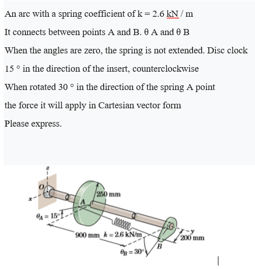
An arc with a spring coefficient of k = 2.6 kN / m ' It connects between points A and B. 0 A and 0 B When the angles are zero, the spring is not extended. Disc clock 15 ° in the direction of the insert, counterclockwise When rotated 30 ° in the direction of the spring A point the force it will apply in Cartesian vector form


Q: The value of the spring index for a helical spring is 10. Calculate the outer diameter of the spring…
A: Given Data C=10 D=53 mm
Q: A self-aligning ball bearing used in the car manufacturing industry has a basic dynamic load rating…
A:
Q: A bar is attached to the spring at the point C. The left end of the bar is pin supported and can…
A:
Q: 1.26 Find the equivalent spring constant of the system shown in Fig. 1.82.
A:
Q: A planar closed kinematic chain is formed with rigid links PQ = 2.0 m, QR = 3.0 m, RS = 2.5 m and…
A: Given data: PQ=2.0 mQR=3.0 mRS=2.5 mSP=2.7 m Need to find that which link should fixed to obtain the…
Q: A bar is attached to the spring at the point C. The left end of the bar is pin supported and can…
A:
Q: Part C - Determining the displacement of a spring The cable segment attached to the spring is at an…
A: Given:- Part C:
Q: The shaft is massless. A thin attached triangular mass ‘m’ is mounted on the shaft. Rotational speed…
A: given that , shaft is massless Rotational speed of the shaft = ω the motion equation for static…
Q: Q.1. PQRS is a four bar chain with link PS fixed. The lengths of the links are PQ = 62.5 mm : QR =…
A:
Q: Sketch the kinematic diagram of the following mechanism shown and give brief description on how each…
A: Since you have asked multiple questions, we will solve the first question for you. If you want any…
Q: A shaft is to be designed for a linkage of a windshield wiper mechanism for a truck as shown in…
A:
Q: Figure 2 Question 3 The combined pulleys in Figure 3 use friction to transmit motion. If block A has…
A:
Q: A punch punches a 1-in. diameter hole in a steel plate % inch thick every 10 sec. The actual…
A:
Q: 4. Find the equivalent spring constant of the system shown. 00000
A: The figure for system of spring connected in parallel and series is given below,
Q: Required information The figure shows a weapon called a battering ram (modern large battering rams…
A:
Q: A homogeneous slender bar AB of mass m and length L is released from rest in the position shown in…
A:
Q: 7. A shaft carries three pulleys A, B and C, the pulleys B and C being 4 ft. and 7 ft. from A. The…
A:
Q: The free end of a torsional spring deflects through 90° when subjected to a torque of 4 N-m. The…
A:
Q: Find the equivalent spring stiffness of the systems shown below
A: a) Reducing all the parallel springs into single equivalent springs, k1=k+2k=3kk2=k+k+k2=2.5k
Q: The value of the spring index for a helical spring is 14. Calculate the outer diameter of the spring…
A:
Q: 1 4 ind the degree of freedom (F) of the mechanism in the figure.
A: Degree of freedom is defined as a number of input required in a mechanism to get the constrained…
Q: REFER THE ATTACHED FIGURE. The shaft is massless. Two thin attached semi-circular discs of mass…
A: Given, Mass of the semicircular discs , m = 1 kg Angular velocity of rotation ,ω = 120 rad/s
Q: 500 rpm, the follower is to be held against the cam by a helical compression spring with a force…
A: Given data- 1.cam running at =500 rpm 2.force on helical spring =80 lb-160 lb 355.8 N-711.7 N…
Q: A steel wire 2 mm diameter is chucks 1 m apart. The wire weighs 0.24 N/m. The flexural stiffness is…
A: GIVEN DATA DIAMETER OF WIRE D=2mm LENGTH L=1m WEIGHT OF WIRE W=0.24N/m FLEXURAL STIFFNESS EI…
Q: Q2. A shaft is supported by two bearings placed 1.2 m apart. A pulley of diameter De meter is…
A: Given:Distance between bearings=1.2 mDiameter of C=650 mm, Radius=325 mmDC=0.65 m RC=0.325…
Q: Question 2. In the Figure given below, when angular displacements are exactly equal to zero, he…
A: Since the pendulums are connected by spring they are subjected to spring force Fs. Also, Fs∝…
Q: A shaft carries three pulleys, A, B and C, the pulleys B and C being 1.2 m and 2.1 m from A. The…
A: Given data: Distance of pulley B from A = 1.2 m Distance of pulley C from A =…
Q: 1. Disk 2. Disk 2000 грm 212 212 a =b =c = 300 mm 30 e12 30 l = 200 mm A
A: Given : Solution : The angular velocity is given as:
Q: Part C- Determining the displacement of a spring The cable segment attached to the spring is at an…
A: Given: ϕ=50° θ =70° TBD=3408N
Q: A shaft is supported by two bearings placed 1.2 m apart. A pulley of diameter Dc meter is mounted at…
A:
Q: A bar is attached to the spring at the point C. The left end of the bar is pin supported and can…
A:
Q: A spring made from a wire of 2.5 mm diameter and 750 N/sq. mm. as its working stress Mean diameter…
A:
Q: the rod vertical in a stable position the minimum value of spring constant K needed is
A: GIVEN DATA; Let the weight be displaced from equilibrium position ,then
Q: An additional design factor of 2.0 is required. What is the design factor used the design of springs…
A:
Q: A bar is attached to the spring at the point C. The left end of the bar is pin supported and can…
A:
Q: . In a mechanism shown in Fig. 1, the crank OA is 100 mm long and rotates clockwise about t 120…
A:
Q: A bar is attached to the spring at the point C. The left end of the bar is pin supported and can…
A:
Q: 1. Determine the degrees of freedom of the mechanism shown in figure (a) and (b) using Kutzbach…
A: Solution: Note: Dear Student! As per our guidelines, we are only allowed to answer a single…
Q: A shaft is supported by two bearings placed 1.2 m apart. A pulley of diameter Dc meter is mounted at…
A: First. draw the top view diagram of the two pulleys: The value of tension T1 is given as 2.25 kN.…
Q: PROBLEM: 7 Calculate the dimensions of helical spring for a spring loaded safety valve from the…
A:
Q: A bar is attached to the spring at the point C. The left end of the bar is pin supported and can…
A: Given data: LAB=3 mLAC=2 mM=30 N.mg=9.81 m/s2 Need to drive the relation between the work, kinetic…
Q: disk can roll in the horizontal direction and the pin is above it. The spring has an unstretched…
A:
Q: A bar is attached to the spring at the point C. The left end of the bar is pin supported and can…
A:
Q: A bar is attached to the spring at the point C. The left end of the bar is pin supported and can…
A:
Q: A shaft is supported by two bearings placed 1.2 m apart. A pulley of diameter Dc meter is mounted at…
A:
Q: The picture shows the rear swivel axle bearing design of a 4-wheel wagon. It is known that the speed…
A: Axels are shafts that are used to rotate the wheels. Its function is to transfer power from the…
Q: Ruestion 3 The combined pulleys in Figure 3 use friction to transmit motion. If block A has a linear…
A:
Q: Figure 5 shows a lever ABC pivoted at B and having a mass of 6 kg and a grinding radius of 75 mm at…
A: Given: mass of lever ABC→mABC=6 Kg Grinding radius→r=75 mm=0.075 m Hence moment of inertia of lever…
Q: Detailed drawing of grounded spring with specification given as: Free length 150mm Pitch- 15mm…
A: Grounded spring is the device that stores potential energy. It is elastic in nature and regains its…
Q: In the following system the wheel rolls without sliding. The number N of degrees of free dome of the…
A:


Trending now
This is a popular solution!

Step by step
Solved in 3 steps with 4 images


- A cargo ship is tied down to marine boll arts at a number of points along its length while its cargo is unloaded by a container handling crane. Each bollard is fastened to the wharf using anchor bolts. Three cables having known tension force magnitudes F, = ll0 kN.F, = 85kN.and F, 9OkNare secured to one bollard at a point A with coordinates (0.0.45 m. 0) in the x-r-: coordinate system shown in the figure part b. Each cable force is directed at an attachment point on the ship. Force F, is directed from point A to a point on the ship having coordinates (3 m, 9 m. 0) force F, is directed at a point with coordinates (6.5 m. 8.5 m. 2 m) and force F, is directed at a point with coordinates (8 m. 9 m. S m). The diameter of each anchor bolts is 4 24 mm. (a) Find the reaction forces and reaction moments at the base of the bollard. (b) Calculate the average shear stress in the anchor bolts (in the x-: plane). Assume each bolt cart ics an equal share of the total force.A bar is attached to the spring at the point C. The left end of the bar is pin supported and can rotates about the pin at Point A. The mass of the bar is m=20kg. The total length of the bar is LAB=3m and LAC=2m. Point A is 0.6 m below the ceiling. A clockwise constant couple moment M= 30Nm is applied on the bar so that the bar rotates from the horizontal position with θ=0° to the vertical position with θ=90°. The spring always maintains at the vertical position. The spring’s stiffness coefficient is k=30N/m and its unstretched length is 0.5 m. The acceleration due to gravity g=9.81 m/s2. During the process that the bar rotates from the horizontal position to the vertical position, determine the following. (4) the work done by the reaction force of the pin.____________ (J)A bar is attached to the spring at the point C. The left end of the bar is pin supported and can rotates about the pin at Point A. The mass of the bar is m=20kg. The total length of the bar is LAB=3m and LAC=2m. Point A is 0.6 m below the ceiling. A clockwise constant couple moment M= 30Nm is applied on the bar so that the bar rotates from the horizontal position with θ=0° to the vertical position with θ=90°. The spring always maintains at the vertical position. The spring’s stiffness coefficient is k=30N/m and its unstretched length is 0.5 m. The acceleration due to gravity g=9.81 m/s2. During the process that the bar rotates from the horizontal position to the vertical position, determine the following. (2) ) the work done by the couple moment. __________(J) (two decimal places)
- A bar is attached to the spring at the point C. The left end of the bar is pin supported and can rotates about the pin at Point A. The mass of the bar is m=20kg. The total length of the bar is LAB=3m and LAC=2m. Point A is 0.6 m below the ceiling. A clockwise constant couple moment M= 30Nm is applied on the bar so that the bar rotates from the horizontal position with θ=0° to the vertical position with θ=90°. The spring always maintains at the vertical position. The spring’s stiffness coefficient is k=30N/m and its unstretched length is 0.5 m. The acceleration due to gravity g=9.81 m/s2. During the process that the bar rotates from the horizontal position (state 1) to the vertical position (state 2), determine the following. 5) when use T to represent kinetic energy, V potential energy, U work done and if the bar is at rest at state 1, the principle of work-energy in this case could be expressed as____________ . V1+∑U(1-2)=T2+V2 T1+V1=T2+V2…A bar is attached to the spring at the point C. The left end of the bar is pin supported and can rotates about the pin at Point A. The mass of the bar is m=20kg. The total length of the bar is LAB=3m and LAC=2m. Point A is 0.6 m below the ceiling. A clockwise constant couple moment M= 30Nm is applied on the bar so that the bar rotates from the horizontal position with θ=0° to the vertical position with θ=90°. The spring always maintains at the vertical position. The spring’s stiffness coefficient is k=30N/m and its unstretched length is 0.5 m. The acceleration due to gravity g=9.81 m/s2. During the process that the bar rotates from the horizontal position to the vertical position, determine the following. (3) the potential energy of the spring when AB is vertical__________(J)A bar is attached to the spring at the point C. The left end of the bar is pin supported and can rotates about the pin at Point A. The mass of the bar is m=20kg. The total length of the bar is LAB=3m and LAC=2m. Point A is 0.6 m below the ceiling. A clockwise constant couple moment M= 30Nm is applied on the bar so that the bar rotates from the horizontal position with θ=0° to the vertical position with θ=90°. The spring always maintains at the vertical position. The spring’s stiffness coefficient is k=30N/m and its unstretched length is 0.5 m. The acceleration due to gravity g=9.81 m/s2. During the process that the bar rotates from the horizontal position to the vertical position, determine the following. (1) if datum is set as when θ=90°, the gravational potential energy of the bar when AB is horizontal will be ____________(J) (two decimal places)
- Can anyone help me with this question. The Motor (J1=0.46 kg‐m2) is connected to a gearbox (J2 =0.27 kg‐m2 and J3=0.17 kg‐m2) by a steel shaft. The output of the gearbox is connected to a turbine (J4=0.37 kg‐m2 by a second steel shaft. The shafts are supported by bearings (not shown). The gearing in the gearbox is such that theta3=‐2.7theta2. Use Lagrange methods to determine the equation of motion for the system including the flexibility of the shafts, using variables of theta 1, theta 3, theta 4 based on changing theta 3.Find the equivalent torsional spring constant (up to two decimal points) of the system shown in the figure. Given : R = 0.2 m k1=1 kN.m/rad, k2 = 2 kN.m/rad , k3 = 3 kN.m/rad , k4 = 4 kN.m/rad , k5 = 5kN/m and k6 = 3.0 kN/mA shaft turning at a uniform speed carries two uniform discs A and B of masses 10kg and 8kg respectively. The centres of the mass of the discs are each 2.5mm from the axis of rotation. The radii to the centres of mass are at right angles. The shaft is carried in bearings C and D between A and B such that AC = 0.3m, AD = 0.9m and AB = 1.2m. It is required to make dynamic loading on the bearings equal and a minimum for any given shaft speed by adding a mass at a radius 25mm in a plane E. Determine: (a) The magnitude of the mass in plane E and its angular position relative to the mass in plane A (b) The distance of the plane E from plane A (c) The dynamic loading on each bearing when the mass in plane E has been attached and the shaft rotates at 200 rev/min. For the bearing loads in the opposite direction determine all the unknown values. For the bearing loads in the same direction, show the diagrams and equations only to use for a possible solution.
- A shaft turning at a uniform speed carries two uniform discs A and B of masses 10kg and 8kg respectively. The centres of the mass of the discs are each 2.5mm from the axis of rotation. The radii to the centres of mass are at right angles. The shaft is carried in bearings C and D between A and B such that AC = 0.3m, AD = 0.9m and AB = 1.2m. It is required to make dynamic loading on the bearings equal and a minimum for any given shaft speed by adding a mass at a radius 25mm in a plane E. USING THE METHOD OF DRAWING m*r and m*r*l diagram Determine: The magnitude of the mass in plane E and its angular position relative to the mass in plane A The distance of the plane E from plane A The dynamic loading on each bearing when the mass in plane E has been attached and the shaft rotates at 200 rev/min. For the bearing loads in the opposite direction determine all the unknown values. For the bearing loads in the same direction, show the diagrams and equations only to use for a possible…A shaft turning at a uniform speed carries two uniform discs A and B of masses 10kg and 8kg respectively. The centres of the mass of the discs are each 2.5mm from the axis of rotation. The radii to the centres of mass are at right angles. The shaft is carried in bearings C and D between A and B such that AC = 0.3m, AD = 0.9m and AB = 1.2m. It is required to make dynamic loading on the bearings equal and a minimum for any given shaft speed by adding a mass at a radius 25mm in a plane E. Determine: The magnitude of the mass in plane E and its angular position relative to the mass in plane A The distance of the plane E from plane A PS – Use graphical methods to solve the balancing problemA shaft turning at a uniform speed carries two uniform discs A and B of masses 10kg and 8kg respectively. The centres of the mass of the discs are each 2.5mm from the axis of rotation. The radii to the centres of mass are at right angles. The shaft is carried in bearings C and D between A and B such that AC = 0.3m, AD = 0.9m and AB = 1.2m. It is required to make dynamic loading on the bearings equal and a minimum for any given shaft speed by adding a mass at a radius 25mm in a plane E. Determine: The dynamic loading on each bearing when the mass in plane E has been attached and the shaft rotates at 200 rev/min. For the bearing loads in the opposite direction determine all the unknown values. For the bearing loads in the same direction, show the diagrams and equations only to use for a possible solution. PS – Use graphical methods to solve the balancing problem