Analyze the given beam that is subjected to a bending moment of 20 kg-m. Find the maximum stress induced in the beam. Figure a
Q: Find the maximum bending stress in the rectangular wooden beam, if the maximum moment is 28 kNm and…
A: Answer: The maximum bending stress in the rectangular wooden beam is 5 MPa.
Q: The beam shown has an second moment of area of 9,500,000 mm4 and a controlling section modulus of…
A:
Q: For the cantilever beam shown. find the value of Torsion stress at point E :due to Torque
A: Given:P=2 KNPt=4 KNT=6 KN.mL=10 md=100 mm
Q: Calculate the maximum displacement (U max), the maximum bending moment Mmax, and the maximum stress…
A:
Q: Determine the equations that allow estimating the shear (V) and the bending moment (M) in the str
A: Given:
Q: beam having section modulus 5000mm3 is subjected to a bending moment of 20kNmm. Find the maximum…
A:
Q: Calculate the shear stress of the beam in the figure at point “a”?
A: Moment of inertia of an area is defined as the product of area and the distances of its center from…
Q: Find the maximum moment for the given beam below. 3K/ft 12K 16K 16K 2K/ft T
A:
Q: Q2) Beam structure as shown above goes under internal moment of M = 5 kN m. Find (Omax)t and…
A:
Q: Draw Shear and Moment Diagrams for each of the beams below and find max bending stress. Every beam…
A:
Q: Ql: For the simply supported beam shown below, calculate the maximum stresses in the steel and wood…
A: To calculate the N.A. of the section:
Q: Calculate the largest allowable load P that can be applied to the beam shown below if the maximum…
A:
Q: For the beam shown below ________ kN-m is the bending moment at its fixed end a. 0 b. -3 x 10⁵ c.…
A: To find the bending moment of the given cantilever beam; W = 1.5 kN/m L = 20 m
Q: Find the maximum shear and normal ctress Find moment of inertia.. 7
A: Let force acting on the beam is P = 10 kN. The given section is as shown below, The area of the…
Q: A beam with the cross-section shown is carrying a bending moment of M. Calculate the maximum bending…
A:
Q: find the maximum bending stress in the aluminum plate.
A:
Q: A beam has a cross-sectional area as shown in the first figure. The lõàdš on the Bea moment diagram…
A:
Q: Calculate the shear force and bending moment for the beam subjected to the loads as shown in the…
A:
Q: Find the absolute maximum bending stress in the beam shown in the figure below. (Figure 3) The beam…
A:
Q: For the beam shown below, Find the bending stress at point A. 16 50 kN 22 + 3 m 3 m
A:
Q: Find the internal bending force at section 1 m from the roller support shown in the figure
A:
Q: A thin strip of hard copper (E = 16,000 ksi) having length L= 90 in, and thickness t=3/32 in. is…
A: Given data:- Modulus of elasticity, E=16000ksi=110.316GPa Length of strip, l=90in=2.286m thickness,…
Q: of the beam are breadth, b = 35 mm and depth d = 125 mm. Calculate the maximum bending stress and…
A:
Q: If the allowable bending stress is a = 247 MPa, find the magnitude of the maximum internal bending…
A:
Q: For the next Beam in Cantiléver; Calculate the Maximum Compressive and Tensile Stresses Due to…
A:
Q: For the beam cross-section shown, (a) find the maximum bending stresses of the beam if the bending…
A:
Q: Q: The following beam shows loading by two spate point loads. Find the moment in the beam ? and…
A: Find the maximum stress.
Q: A overhang beam hanged at B(6m) has two loads of 8 & 4 kn at 6 and 9 m. Calulate its moment using…
A:
Q: If Mz = 715 kip-ft, find the magnitude of the bending stress at a point H. For the beam cross…
A: Given data: Moment of Inertia = Iz = 60436 in4 Mz = 715 kip-ft The figure is missing in the data. By…
Q: The box beam shown in Figure 1 is subjected to an internal moment of M= 4 kN.m which is directed as…
A: Solution.jpg
Q: Draw the shear force and bending diagrams for the beam shown in figure. moment
A: Given data: A cantilever beam with 3 point loads, UDL and a couple.
Q: For the beam shown below, determine the maximum bending stress in the beam. sketch the section…
A:
Q: A beam has a bending moment of 3.5 kN-m applied to a section with a hollow circular cross-section of…
A:
Q: Calculate the support reaction moment at the clamped part of the cantilever beam and find the…
A:
Q: Q/Find the maximum tensile and compressive flexure stresses for the cantilever beam shown in Fig. *…
A:
Q: SKN | SKN A simply supported beam subjected to three point loads as shown in the Figure . Draw shear…
A:
Q: Analyze the simply supported beam shown in figure-6, by drawing its Shear Force and Bending Moment…
A:
Q: 70 mm Mx. G 165 mm Mx = 79KNM %3D 60 mm 190m The bending moment Mx offects the cross section of the…
A: In this question we have to calculate normal stress at three different location on the T section
Q: A beam has a bending moment of 3.5 kN-m applied to a section with a hollow circular cross-section of…
A: Since you have asked a question with multiple parts in a single request we would be answering only…
Q: The shaft in Figure B1 is subjected to the concentrated forces shown. T sleeve bearings at A and B…
A:
Q: Determine the length L of the center portion of the bar as shown on Figure Q3 so that the maximum…
A:
Q: Figure (a) shows a cantilever box beam that is subjected to a pure bending moment M=3kN.m about the…
A:
Q: Draw the shear force diagram (SFD) and bending moment diagram (BMD) for the beam shown in figure. 2…
A:
Q: If Mz = 200 kip-ft, find the magnitude of the bending stress at a point H. For the beam cross…
A:
Q: Find the section modulus for a beam of circular cross section with the diameter of 90mm. The section…
A: Diameter(D)=90mm
Q: Calculate the internal shear force and the internal bending moment for the beam at every point x,…
A: We will answer the first question since the exact one was nor specified. Please subit the new…
Q: For the beam shown in the figure below, determine the equation bending moment along the beam then…
A:
sovle the question given in the pic.
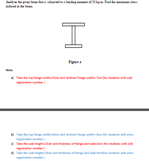
Step by step
Solved in 5 steps with 1 images
- The cross section of a sand wie h beam consisting of aluminum alloy faces and a foam core is shown in the figure. The width b of the beam is 8.0 in, the thickness I of the faces is 0.25 in., and the height hcof the core is 5.5 in. (total height h = 6.0 in). The moduli of elasticity are 10.5 × 10⁶ psi for the aluminum faces and 12.000 psi for the foam core. A bending moment M = 40 kip-in. acts about the z axis. Determine the maximum stresses in the faces and the core using (a) the general theory for composite beams and (b) the approximate theory for sandwich beams.Obtain a formula for the ratio c/maxof the deflection at the midpoint to the maximum deflection for a simple beam supporting a concentrated load P (see figure). From the formula, plot a graph of c/max versus the ratio a/L that defines the position of the load (0.5 < a/L < ) What conclusion do you draw from the graph? (Use the formulas of Example 9-3.)A beam made up all woun equal leg angles is subjected to a bending moment M having its vector .u an angle (i) lo lire axis (see figure paria). (a) For the position shown in lire figure, determine lire orienlalion of lire neulral axis and calculate lire maximum tensile s'av-s ir, and maximum compressive stress (b) The two angles are now inverted and attached back-lo-back lo lorn, a lintel beam that supports two courses of brick facade i see figure part b). Find the new orientation of the neutral axis and calculate the maximum tensile slress r. a::d maximum compressive s'avsrr . in I he beam using 6 = 30° and M = 30 kip-in.
- A seesaw weighing 3 lb/ft of length is occupied by two children, each weighing 90 lb (see figure). The center of gravity of each child is 8 ft from the fulcrum. The board is 19 ft long, 8 in. wide, and 1.5 in. thick. What is the maximum bending stress in the board?A two-axle carriage that is part of an over head traveling crane in a testing laboratory moves slowly across a simple beam AB (sec figure). The load transmitted to the beam from the front axle is 2200 lb and from the rear axle is 3800 lb. The weight of the beam itself may be disregarded. Determine the minimum required section modulus S for the beam if the allowable bending stress is 17,0 ksi, the length of the beam is 18 ft, and the wheelbase of the carriage is 5 ft. Select the most economical I-beam (S shape) from Table F-2(a), Appendix F.A steel beam of rectangular cross section is 40 mm wide and 80 mm high (see figure). The yield stress of the steel is 210 MPa, (a) What percent of the cross-sectional area is occupied by the clastic core if the beam is subjected to a bending moment of 12.0 kN · m acting about the z axis? (b) What is the magnitude of the bending moment that will cause 50% of the cross section to yield?
- -3 The deflection curve for a simple beam AB (see figure) is given by v=q0x360LEI(7L410L2x2+3x4) Describe the load acting on the beam.The cross section of a rectangular beam having a width b and height h is shown in part a of the figure. For reasons unknown to the beam designer, it is planned to add structural projections of width b/9 and height d/9 the top and bottom of the beam (see part b of the figure). For what values of d is the bending-moment capacity of the beam increased? For what values is it decreased?A C 200 x 17.1 channel section has an angle with equal legs attached as shown; the angle serves as a lintel beam. The combined steel section is subjected to a bending moment M having its vector directed along the z axis, as shown in the figure. The cent roi d C of the combined section is located at distances xtand ycfrom the centroid (C1) of the channel alone. Principal axes yl and yvare also shown in the figure and properties Ix1,Iy1and 0pare given. Find the orientation of the neutral axis and calculate the maximum tensile stress exand maximum compressive stress if the angle is an L 76 x 76 x 6.4 section and M = 3.5 kN - m. Use the following properties for principal axes for the combined section:/^, = 18.49 X 10⁶ nrai4,/;| = 1.602 X 106 mm4, ep= 7.448*(CW),_r£ = 10.70 mm,andvf= 24.07 mm.
- The hollow box beam shown in the figure is subjected to a bending moment M of such magnitude that the flanges yield but the webs remain linearly elastic. (a) Calculate the magnitude of the moment M if the dimensions of the cross section are A = 15 in., A] = 12.75 in., h = 9 in., and ey =7.5 in. Also, the yield stress is eY = 33 ksi. (b) What percent of the moment M is produced by the elastic core?-6 Calculate the maximum deflection of a uniformly loaded simple beam if the span length L = 2.0 m, the intensity of the uniform load q = 2.0 kN/m, and the maximum bending stress = 60 MPa, The cross section of the beam is square, and the material is aluminum having modulus of elasticity E = 70 GPa. (Use the formulas of Example 9-1.)A composite beam consisting of fiberglass faces and a core of particle board has the cross section shown in the figure. The width of the beam is 2,0 in., the thickness of the faces is 0,10 in., and the thickness of the core is 0.50 in. The beam is subjected to a bending moment of 250 lb-in, acting about the - axis. Find the maximum bending stresses tr(and ctc in the faces and the core, respectively, if their respective moduli of elasticity are 4 x 10⁶ psi and 1.5 x 10⁶ psi.