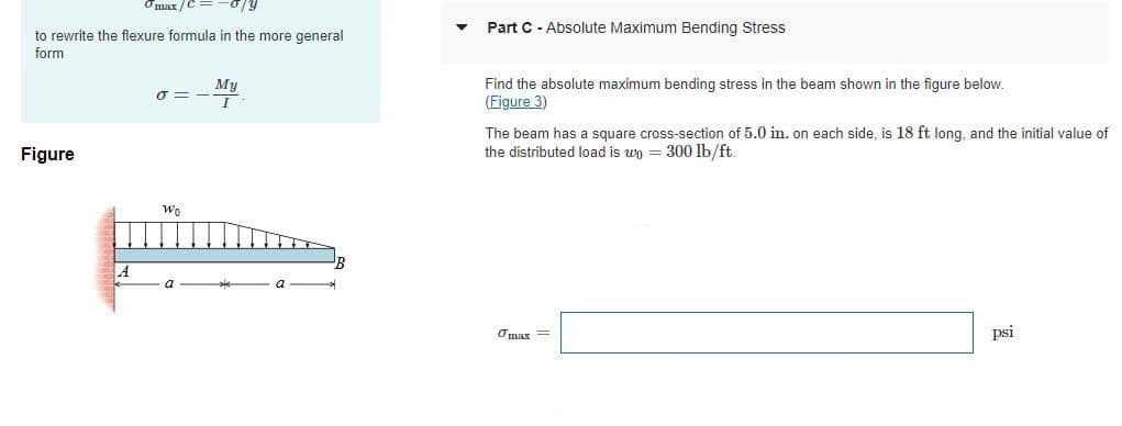
Find the absolute maximum bending stress in the beam shown in the figure below. (Figure 3) The beam has a square cross-section of 5.0 in. on each side, is 18 ft long, and the initia the distributed load is un = 300 lb/ft.
Q: For the loaded beam shown in Figure Q6 below, consider section M-M and detemine the following: 6.1…
A: Given Data: Length of the beam, L=0.4+0.3+0.4=1.1 m
Q: A rectangular plate with notches (see figure) has dimensions h=5.75 in, h1 = 5 in and the plate…
A:
Q: A bending moment of M=150 kips-in is applied at the cross section of beam shown in Figure Question…
A:
Q: The figure shows a reinforced wooden beam with an aluminum channel section as seen in the figure.…
A: Given: The dimension of cross section is 6 in. by 10 in. Thickness is 0.25 in. Allowable stress in…
Q: A cantilever beam AB with rectangle cross section has a longitudinal hole drilled throughout its…
A:
Q: Figure 1a shows a simply supported beam, AB of length L = 5.6 m, with a uniform distributed load of…
A:
Q: The cross-sectional dimensions of the beam shown in Figure are ro = 115 mm and ri = 95 mm. Given Mz…
A: Moment of inertia is given asI=π64D4-d4I=π642×1154-2×954I=73.39×106 mm4perpenficular distance…
Q: Ql: For the simply supported beam shown below, calculate the maximum stresses in the steel and wood…
A: To calculate the N.A. of the section:
Q: For the beam shown below ________ kN-m is the bending moment at its fixed end a. 0 b. -3 x 10⁵ c.…
A: To find the bending moment of the given cantilever beam; W = 1.5 kN/m L = 20 m
Q: Determine the largest allowable value of P if the bending stress for simply supported beam (shown in…
A:
Q: Q: Find the value of W which can be applied to the beam shown in figure below. if the maximum…
A:
Q: For the cantilever beam with uniformly distributed load shown in Figure find: d. The moment of…
A: Consider the given cantilever beam. Calculate the reaction at the fixed end. R=16 kN/m5 mR=80 kN…
Q: The beam ABCD with a rectangular cross section carries the loading shown in the figure. Determine…
A:
Q: Example 4 The simply supported beam in Figure below has a rectangular 3kN cross section 100 mm wide…
A: Solution: To find support reactions at A and B, considering static equilibrium,…
Q: A steel beam is built up from a W 410 x 85 wide flange beam and two 180 mm x 9 mm cover plates (see…
A: To find: The required bolt spacing in longitudinal direction. Given: The allowable load in each bolt…
Q: The composite beam in the figure is made of steel and aluminum. Beam In steel and aluminum as it is…
A: Given: Esteel=210GPa Eal=70GPa M=2kNm Solution: The position of the neutral axix is exactly at the…
Q: The distributed load on the T-section beam in the figure is w = 100 kN/m. The tensile stress that…
A: Bending stress in beams When external load acts on beam shear force and bending moment are set up at…
Q: Situation 12: The simply supported beam in FIGURE SOM-008 is fabricated by gluing together three 160…
A: For the given simply supported beam maximum bending stress in the planks = 24 MPa To determine…
Q: A beam simply supported at the ends of a 25-ft span carries a uniformly distributed load of 1000…
A:
Q: F W 50 mm 20 mm -2 m
A: Free body diagram of the beam:
Q: For the simply supported beam shown in the figure, the location of maximum bending moment from left…
A: From the moment about the right support, From symmetry,
Q: The figure below shows a hollow circular beam with an outside diameter of 150 mm and a wall…
A:
Q: Problem 1) Cross section of a beam was shown in the below figure. Suppose that this beam is…
A: Given: The bending moment, M = 10 kN.m
Q: A wood beam carries the loading shown in the figure, calculate the magnitude of the bending stress…
A:
Q: Consider the beam shown in the figure. Suppose that the distributed load w = 650 lb/ft . Follow the…
A: Solution ; As the loading is symmetric, so reaction at the support will be equal :…
Q: The cross-section of beam shown in Figure Q2 (centroid in red) is subjected to pure bending. Taking…
A:
Q: Calculate the maximum shear stress τmax and the maximum bending stress σmax in a wood beam (see…
A: Draw the free body diagram of simple supported beam-
Q: Q: For the loaded simply supported beam shown in figure below, if the allowable bending stress is…
A:
Q: Q2: For the beam shown in figure below, find the bending stress of beam at point A. When I= 120*10*…
A: Bending equation is given as: MI=σy=ER where, M is the bending moment I is the moment of…
Q: 1.0OKN/m NA 387mm 21.Imm Web 150mm 398mm 6m S0mim Fig. P6. 1 Fig. P6. 2 6.2 For the cantilever beam…
A: Given Values Length of the cantilever is 6 m Triangular load applying on the beam is 1.0 kN/m Length…
Q: Consider the beam shown in sketch below, hinge supported at point A and roller supported at point D.…
A: Considering the cross-section of the beam The web is denoted as 1 and flange is denoted as 2
Q: A thin strip of hard copper (E = 16,000 ksi) having length L= 90 in, and thickness t=3/32 in. is…
A: Given data:- Modulus of elasticity, E=16000ksi=110.316GPa Length of strip, l=90in=2.286m thickness,…
Q: For the cantilever beam with uniformly distributed load shown in Figure find: a. The maximum shear…
A: note: according to Bartleby guideline, we solve the first three-part of the question please repost…
Q: For the beam shown in the figure, find the shear stress at a point 25 mm above the bottom of the…
A: Given, A simply supported beam with point load , P =14 KN Moment of inertia of the cross section ,…
Q: Box-section cantilever beam in the figure bears. Safety stresses in pressure and tension…
A: “Since you have posted a question with multiple sub-parts, we will solve first two subparts for you.…
Q: A circular solid cross-section cantilever is fixed at one end and bears a concentrated load P at the…
A: Given Load, P = 30 kN Length, l = 2 m Find Maximum bending stress
Q: Example 1 The bar is subjected to a moment of M = 17.5 N.m. If r = 5 mm, determine the maximum…
A: Introduction: Bending stress is the typical stress that an item experiences when subjected to a…
Q: Problem 2 For the beam shown in the figure A) Draw the shear-force and bending-moment diagrams for…
A:
Q: 9 A rectangular cross section beam of width 0.25 m and depth 0.4 m is subjected to a bending moment…
A: Calculated distance from the top surface where normal stress will be zero.
Q: The composite beam shown in the Figure below is formed of a wood beam and a steel reinforcing plate.…
A:
Q: For the fixed-ended beam shown in figure below, each end moment equals: P A В L/2- L/2- P/2 O P/8…
A: For the fixed-ended beam shown in figure below, each end moment equals: P/2 P/8 P/16 P/4
Q: A rectangular section of dimensions 120 x 200 mm is used as a beam on a 3 m span. If the beam is…
A: Simply Supported beam : it is the basic structure with pinned support or roller support at the end…
Q: Rectangular section and width given in the figure The bending safety stress of the beam with b = 150…
A:
Q: aluminum steel t A composite beam is a built-up section made of aluminium and reinforced with a…
A:
Q: Determine the maximum bending stress in the given figure below.
A: Given: The beam height, h = 200 mm The beam width, b = 50 mm The depth of neutral axis, c = 100 mm
Q: Q: For the cantilever beam with uniformly distributed load shown in Figure find; a The maximum shear…
A: As per company policy, we are restricted to solve only the first three sub-part of one question at a…
Q: A simply supported beam is subjected to a distributed load of wi=640 N/m and a point load pi = 940…
A:
Q: A beam had an isosceles triangular cross section (see figure below). The maximum flexural stress is…
A: Given Data The maximum stress applied on the beam is: σ=90 MPa The Base of the triangle beam is:…
Q: The cross-sectional dimensions of the beam shown in Figure are ro = 115 mm and ri = 95 mm. Given Mz…
A:
if not sure skip , i have posted many times , will downvote if wrong
Trending now
This is a popular solution!
Step by step
Solved in 2 steps with 2 images
- The cross section of a sand wie h beam consisting of aluminum alloy faces and a foam core is shown in the figure. The width b of the beam is 8.0 in, the thickness I of the faces is 0.25 in., and the height hcof the core is 5.5 in. (total height h = 6.0 in). The moduli of elasticity are 10.5 × 10⁶ psi for the aluminum faces and 12.000 psi for the foam core. A bending moment M = 40 kip-in. acts about the z axis. Determine the maximum stresses in the faces and the core using (a) the general theory for composite beams and (b) the approximate theory for sandwich beams.The cross section of a rectangular beam having a width b and height h is shown in part a of the figure. For reasons unknown to the beam designer, it is planned to add structural projections of width b/9 and height d/9 the top and bottom of the beam (see part b of the figure). For what values of d is the bending-moment capacity of the beam increased? For what values is it decreased?A beam supporting a uniform load of intensity q throughout its length rests on pistons at points A, C and B (sec figure). The cylinders are filled with oil and are connected by a tube so that the oil pressure on each piston is the same. The pistons at A and B have diameter d1and the piston at C has diameter D2. (a) Determine the ratio of d2to d1so that the largest bending moment in the beam is as small as possible. Under these optimum conditions, what is the largest bending moment Mmaxin the beam? What is the difference in elevation between point C and the end supports?
- A beam with a channel section is subjected to a bending moment M having its vector at an angle 0 to the 2 axis (see figure). Determine the orientation of the neutral axis and calculate the maximum tensile stress et and maximum compressive stress ecin the beam. Use the following data: C 8 × 11.5 section, M = 20 kip-in., tan0=l/3. See Table F-3(a) of Appendix F for the dimensions and properties of the channel section.A hollow box beam with height h = 9.5 in., inside height/i, = 8.0 in., width? = 5,25 in., and inside width =4.5 in. is shown in the figure. Assuming that the beam is constructed of steel with yield stress ty= 42 ksi calculate the yield moment My, plastic moment MPand shape factor f.Two identical, simply supported beams AB and CD are placed so that they cross each other at their midpoints (sec figure). Before the uniform load is applied, the beams just touch each other at the crossing point. Determine the maximum bending moments (mab)max* and (MCD)max beams AB and CD, respectively, due to the uniform load if the intensity of the load is q = 6.4 kN/m and the length of each beam is L = 4 m.
- -1 through 5.10-6 A wide-flange beam (see figure) is subjected to a shear force V. Using the dimensions of the cross section, calculate the moment of inertia and then determine the following quantities: The maximum shear stress tinixin the web. The minimum shear stress rmin in the web. The average shear stress raver (obtained by dividing the shear force by the area of the web) and the ratio i^/t^. The shear force i^/t^ carried in the web and the ratio V^tV. Note: Disregard the fillets at the junctions of the web and flanges and determine all quantities, including the moment of inertia, by considering the cross section to consist of three rectangles. 5.10-6 Dimensions of cross section: b = 120 mm, a = 7 mm, h = 350 mm, hx= 330 mm, and K=60kN.A rectangular beam with semicircular notches, as shown in part b of the figure, has dimensions h = 120 mm and h1= 100 mm. The maximum allowable bending stress in the plastic beam is emix = 6 M Pa, and the bending moment is M = 150 N · m. Determine the minimum permissible width bminof the beam.-1 through 5.10-6 A wide-flange beam (see figure) is subjected to a shear force V. Using the dimensions of the cross section, calculate the moment of inertia and then determine the following quantities: The maximum shear stress tinixin the web. The minimum shear stress rmin in the web. The average shear stress raver (obtained by dividing the shear force by the area of the web) and the ratio i^/t^ The shear force carried in the web and the ratio V^tV. Noie: Disregard the fillets at the junctions of the web and flanges and determine all quantities, including the moment of inertia, by considering the cross section to consist of three rectangles. 5.10-3 Wide-flange shape, W 8 x 28 (see Table F-L Appendix F); V = 10 k
- -1 through 5.10-6 A wide-flange beam (see figure) is subjected to a shear force V. Using the dimensions of the cross section, calculate the moment of inertia and then determine the following quantities: The maximum shear stress tinixin the web. The minimum shear stress rmin in the web. The average shear stress raver (obtained by dividing the shear force by the area of the web) and the ratio i^/t^ The shear force carried in the web and the ratio V^tV. Note: Disregard the fillets at the junctions of the web and flanges and determine all quantities, including the moment of inertia, by considering the cross section to consist of three rectangles. 5.10-4 Dimensions of cross section: b = 220 mm, f = 12 mm, h = 600 mm, hx= 570 mm, and V = 200 kN.-1 through 5.10-6 A wide-flange beam (see figure) is subjected to a shear force V. Using the dimensions of the cross section, calculate the moment of inertia and then determine the following quantities: The maximum shear stress tinixin the web. The minimum shear stress rmin in the web. The average shear stress raver (obtained by dividing the shear force by the area of the web) and the ratio i^/t^ The shear force carried in the web and the ratio K b/K. Note: Disregard the fillets at the junctions of the web and flanges and determine all quantities, including the moment of inertia, by considering the cross section to consist of three rectangles. 5.10-2 Dimensions of cross section: b = 180 mm, v = 12 mm, h = 420 mm, i = 380 mm, and V = 125 kN.-1 through 5.10-6 A wide-flange beam (see figure) is subjected to a shear force V. Using the dimensions of the cross section, calculate the moment of inertia and then determine the following quantities: The maximum shear stress tinixin the web. The minimum shear stress rmin in the web. The average shear stress t (obtained by dividing the shear force by the area of the web) and the ratio tmax/taver. The shear force Vweb/V carried in the web and the Vweb/V. Note: Disregard the fillets at the junctions of the web and flanges and determine all quantities, including the moment of inertia, by considering the cross section to consist of three rectangles. 5.10-1 Dimensions of cross section: b = 6 in,, ï = 0.5 in., h = 12 in,, A, = 10.5 in., and V = 30 k.