Analyze the simply supported beam shown in figure-6, by drawing its Shear Force and Bending Moment Diagram. (CLO-2) 50 N 150 N.m 2m Rp 4 m 2 m RA Figure - 6
Analyze the simply supported beam shown in figure-6, by drawing its Shear Force and Bending Moment Diagram. (CLO-2) 50 N 150 N.m 2m Rp 4 m 2 m RA Figure - 6

Mechanics of Materials (MindTap Course List)
9th Edition
ISBN:9781337093347
Author:Barry J. Goodno, James M. Gere
Publisher:Barry J. Goodno, James M. Gere
Chapter4: Shear Forces And Bending Moments
Section: Chapter Questions
Problem 4.5.9P: A simply supported beam ABC is loaded at the end of a bracket BDE (see figure). Draw axial-force,...

Related questions

Question
100%
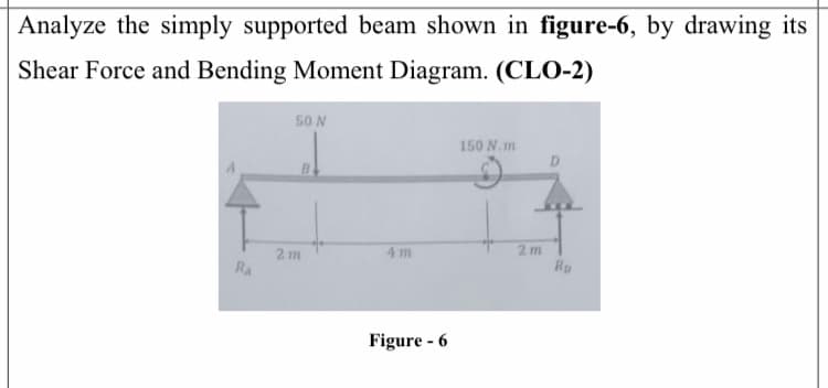
Transcribed Image Text:Analyze the simply supported beam shown in figure-6, by drawing its
Shear Force and Bending Moment Diagram. (CLO-2)
50 N
150 N.m
2m
Rp
4 m
2 m
RA
Figure - 6
Expert Solution
This question has been solved!
Explore an expertly crafted, step-by-step solution for a thorough understanding of key concepts.

This is a popular solution!

Trending now
This is a popular solution!

Step by step
Solved in 4 steps with 4 images

Knowledge Booster


Learn more about
Need a deep-dive on the concept behind this application? Look no further. Learn more about this topic, mechanical-engineering and related others by exploring similar questions and additional content below.Recommended textbooks for you
Mechanics of Materials (MindTap Course List)
Mechanical Engineering
ISBN:
9781337093347
Author:
Barry J. Goodno, James M. Gere
Publisher:
Cengage Learning
Mechanics of Materials (MindTap Course List)
Mechanical Engineering
ISBN:
9781337093347
Author:
Barry J. Goodno, James M. Gere
Publisher:
Cengage Learning