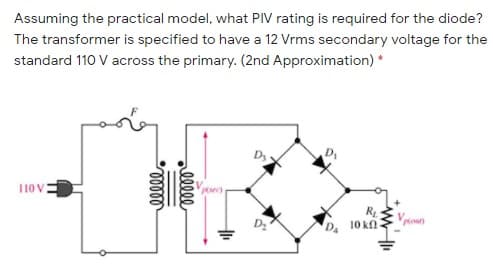
Assuming the practical model, what PIV rating is required for the diode? The transformer is specified to have a 12 Vrms secondary voltage for the standard 110 V across the primary. (2nd Approximation) * D 110 V R 10 kn- out) alll


Q: A Zener diode circuit is shown in Figure Q.1(b). Given Vz = 12 V, (i) Determine I, Vulh and lg…
A: Given Vz = 12 V Izmax = 15 m A. RLmax = Vz/ILmin RLmin = Vz /ILmax
Q: Draw the voltage transfer characteristic for the circuit shown in Figure Q4. Assume that V₂ = 0.7V…
A:
Q: Q2) Consider the circuit below. The diodes D1 and D2 are Si diodes VD,=.7v and R=10K , The Zener…
A: In the circuit Two diode and zerer diode are consist. Voltage drop each diode are given. Draw the…
Q: Given that RI = i0, R2 (Rload) - IKA, LI - 750mH, k - 1,Vi - 220V.f = 60HZ, assume an ideal diode,…
A: A center tapped full wave rectifier is given. It converts AC into pulsating DC.
Q: A full Wave rectifier shown in the circuit has 12OV (rms) 50HZ input through a transformer. RL = 200…
A: Circuit diagram is given as,
Q: (b) If such a circuit is to be used to supply an average of 10 V across the load, calculate the…
A: Full-wave rectifier: This rectifier converts the AC into the DC. If it contains the split winding on…
Q: 3) For the Half-Wave Rectifier circuit shown below, determine: the Transformer Turns ratio, n [ IEEE…
A:
Q: Assuming the practical model, what PIV rating is required for the diode? The transformer is…
A: Given data: VS=12 V RMS
Q: / Consider the circuit shown below with a transformer of 10:1 transformation ratio and the diodes…
A:
Q: The zener diode shown in the circuit below is being used for voltage regulation. Determine the…
A: Redrawing the circuit diagram by marking the current and the voltage as shown below:
Q: A silicon diode has a maximum allowable junction temperature of 150°C. Find the maximum allowable…
A: Given data, Maximum allowable temperature Tj=1500 C Temperature at which maximum power dissipation…
Q: In the circuit given in the figure, find the current passing through the diode in mA since R1 =…
A: The detailed answer is solved below according to the given parameters and instructions in the…
Q: How is the diode and zener diode in the electronic circuit and how they work? indicate the…
A: Given : Note : It is the kind notice that according to the guidelines of the company whenever we…
Q: 5. A diode has a reverse saturation current of 6 x 10¹⁵ A and an ideality factor of 1. If its DC…
A: As per Bartleby policy only one question is to be answered.
Q: In diode reverse biasing the potential barrier and depletion region will increase. True O False The…
A: About diode and it's applications.
Q: Design a DC power supply using FWR to perform the following requirements. Find V_dc, V_rms, -ripple,…
A: Given: Input voltage,Vprimary = 350 V Transformer turn ration = 0.08 = 8100=225 Load resistance, RL…
Q: A thyristor used in a half wave rectifier used 220V , with firing angle 60°, total resistance load…
A: We are authorized to answer three subparts at a time since you have not mentioned which part you are…
Q: A half wave rectifier with is given to an input of 10V peak from a step down transformer. Calculate,…
A: Half wave rectifier given in the circuit, Find the average current Average voltage and rectifier…
Q: transformer. RL = 200 Ohm, If silicon diodes are employed, what is the dc voltage * ?available at…
A:
Q: Q1/ In the circuit shown below, the zener diode used has the following specifications : Vz= 12 volt,…
A:
Q: 3. In the circuit shown below, the knee current of the ideal Zener diode is 10 mA. To maintain 5 V…
A: In the voltage regulator circuit. Find the minimum value of the load resistance? Maximum power…
Q: Q3: A.C. voltage with peak value (Vm-20V) is connected in series with silicon diode and load (R= 500…
A: 1... For silicon Diode. The forward voltage drop of silicon diode is 0.7V. The diode will be forward…
Q: 4670V = Vs R = 200kΩ C = 0.1μF Consider the circuit and parameters illustrated above. If a…
A:
Q: d. Determine the minimum value of R1 to ensure that the Zener diode is in the “on" state. Rs 220 2…
A: Given
Q: For the circuit shown below D1 and D2 are Ideal Diodes, R1 = R2 = R33D2 K2. The output of the…
A: GIVEN DATA:
Q: In a Zener regulated DC power supply, the input to the regulator varies between 15 V and 19 V. The…
A:
Q: Find the current through the diode in the circuit shown. Assume the diode to be ideal. 50 92 R₁ D V…
A:
Q: Consider the design of a DC power supply as shown above with the following requirements and…
A: Since you have posted a question with multiple subparts, we will solve the first three subparts for…
Q: lhe eireuit of Figure T.c, the voltage source is equal to V = 5 V and the load sistor is equal to R…
A:
Q: Q3/ Consider the circuit shown below with a transformer of 10:1 transformation ratio and the diodes…
A:
Q: ii) For the loaded Zener regulator shown in Figure (b), determine the minimum and maximum possible…
A:
Q: The cut-in voltage of the diode shown in the circuit in Figure 1 is Vy = 0.7 V. The diode is to…
A: The cut in voltage for the diode is given as 07V and the diode is in ON position when the power is…
Q: The four semiconductor diodes used in a bridge rectifier circuit have forward resistance which can…
A: Correct option is none of the above
Q: Consider the "Zener diode as a voltage regulator" circuit given below: 1502 D unregulated/ 12 volt…
A: For given Zener diode to operate in a breakdown region is necessary to operate in the reverse-biased…
Q: A silicon diode has a maximum allowable junction temperature of 150°C. Find the maximum allowable…
A:
Q: Sketch i0and v01 for the network below for the input shown (Both diodes are Si. VD=0.7 V). Explain…
A:
Q: VIBO HaO Deg V vrdg = 24Vdo RL 120 Ohm c2
A: It is given Eripplepk-pk= 0.75V Standard average current diode rating : 1A, 2A, 3A, 4A, 5A…
Q: A full Wave rectifier shown in the circuit has 120V (rms) 50 Hz input through a transformer. RL = 2k…
A:
Q: D3 10 V R1 Vp(our) 10 κΩ D2 D4 lll
A: A bridge rectifier is a type of full wave rectifier which makes use of four diodes connected in the…
Q: Design a DC power supply using FWR to perform the following requirements. Find V_dc, V_rms,…
A:
Q: Consider three p -n-junctions as shown below. Say true or false. Write a sentence justifying your…
A:
Q: for the given circuit, input voltage is AC(10,-10)v, R=2KN , diode is ideal. what is the Vout in the…
A: The solution can be achieved as follows.
Q: The zener diode is ideal, find the minimum value of R for which the output voltage remain constant…
A: Let RL is the minimum resistance for breakdown of zener diode.
Q: Vcc R3
A:
Q: Which of the following indicates the correct rms value of the diode current for a 1-o full bridge…
A:
Q: . Consider the diode circuit shown in the figure, where R1 = R2 = 1 kN. v. v.(t) When V3 = 4 V and…
A:
Q: A Zener diode is connected in a voltage regulator circuit as shown in figure.2. The Zener voltage at…
A: Given: At Iz=0, Zener voltage, Vz=15 V Zener incremental resistance, rz=0.2 Ω (a) Load current…
Q: For the circuit shown in the figure D, and D2 are identical diode with ideality factor of unity. The…
A: Given: η=1VT=25 mVIs=1 pA
Q: R1 L1 D1 400 200m D V1 R2 1600 10 he switch is closed for t<0 and opens at t=0. Determine the state…
A:

Step by step
Solved in 2 steps with 2 images

- How is a solid-state diode tested? Explain.Assuming the practical model, what PIV rating is required for the diode? The transformer is specified to have a 12 Vrms secondary voltage for the standard 110 V across the primary. (2nd Approximation)Determine Q-point for the diodes in the circuit given below using the ideal diode model where, R1 = 12.2 kΩ, R2 = 16 kΩ, and R3 = 14 kΩ. (Note: Label the diodes from left to right.)
- In a 1-phase full wave bridge rectifier with Vs = Vm sin ωt, with R load & ideal diodes. The expression for the average value of the output voltage is 2Vm/π Select one: True False3. It is required to design a full-wave rectifier circuit using the circuit shown below to provide an average output vol tage of10 V. find the required turns ratio of the transformer. Assume that a conducting diode has a voltage drop of0.7 V. The ac line vol tage is120 Vrms.The diode current in a p-n junction is modeled exponentially (given below.) When the p-n junction is polarized with 0.7V and 0.75V, the currents flowing through the diode are again measured on the basis of 1.36 mA and 7.20 mA. Accordingly, what is the ideality factor? (Note: Take the thermal voltage as mV)
- A schematic design of a full-wave bridge type power supply is given below. Provide the appropriate values for the inductors, diodes, capacitor and resistors, such that the output DC voltage is 6.2 V and the max. output power for the load resistance is 20 mW (percentage error for output voltage and output power is 2%). AC voltage source: Amplitude=311.13, Freq=60, DC offset= 0. For the rectifier part, choose diodes with an appropriate PIV rating. Show all the formulas and computations involved in acquiring the values for the inductors, diodes, capacitor and resistors. In choosing your Zener diode, consider the output voltage and the output current. Note that the output current should be the minimum Zener current. For the value of the series resistor RS, choose a lower value for less ripple but always consider the required output voltage. The ripple voltage peak-to-peak value should be less than or equal to 1% of the required output voltage. Use the formula below for choosing the value…Draw the V-I characteristic curve of a Ge based Zener diode with Zener breakdown voltage (?z=5 ?). Indicate three different regions of the curve. Subject: Electronic devicesDerive the current equations for the circuit shown below, using the labels as shown.Note that rz here is a model of the parasitic imperfection of the Zener diode.a) IL = ?b) II = ?c) IZ = ?d) What impact does rz have on VL?
- Draw the circuit diagram of a single phase full-wave uncontrolledrectifier with R-load. Describe its principle of operation. Draw thewaveforms of: input voltage, voltage across the load, current throughthe diodes and their voltage. Write the expressions for: the averageoutput voltage Vd, the maximum reverse voltage across the diode and thestandard transformer power. Describe what the difference will be if acapacitor is added in parallel with the load at the output.Consider the full-wave rectifier circuit shown below, where• vS(t) is a sinusoidal signal with a peak value (Vs = 5 V).• Diodes are modelled using constant voltage model with VDO = 0.7 V• The ac line voltage has an rms value of 120 V and a frequency (f) = 60 Hza) Calculate the transformer turns ratio. b) Plot in the same graph signal vS(t) and the output signal vO(t) versus time (t) (show all details including amplitudes, time instances, etc.) c) Calculate the rms value of the output signal vO(t). (hint: sin2(x) = 0.5(1- cos(2x))) d) If a capacitor C=3.58 F is connected across R = 10 k, repeat (b) in a new graphA diode is biased by a 0.9-V dc source, and its current is found to be 100 μA at T = 35◦C. (a) At what temperature will the current double? (b) At what temperature will the current be 50 μA?