The cut-in voltage of the diode shown in the circuit in Figure 1 is Vy = 0.7 V. The diode is to remain biased “on" for a power supply voltage in the range 4 < Vps < 10V. If R¡=1kN and R2=2kQ, calculate the minimum diode current and the maximum power dissipated in the diode. R1 Vout Vin 1 kQ R2 2 kn $ D2
The cut-in voltage of the diode shown in the circuit in Figure 1 is Vy = 0.7 V. The diode is to remain biased “on" for a power supply voltage in the range 4 < Vps < 10V. If R¡=1kN and R2=2kQ, calculate the minimum diode current and the maximum power dissipated in the diode. R1 Vout Vin 1 kQ R2 2 kn $ D2

Chapter59: Motor Startup And Troubleshooting Basics
Section: Chapter Questions
Problem 12SQ: How is a solid-state diode tested? Explain.

Related questions
Question
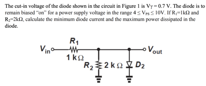
Transcribed Image Text:The cut-in voltage of the diode shown in the circuit in Figure 1 is Vy = 0.7 V. The diode is to
remain biased “on" for a power supply voltage in the range 4 < Vps < 10V. If Rj=1kN and
R2=2kQ, calculate the minimum diode current and the maximum power dissipated in the
diode.
R1
Vin
oVout
1 ko
R22 k2
y D2
Expert Solution
This question has been solved!
Explore an expertly crafted, step-by-step solution for a thorough understanding of key concepts.

Step by step
Solved in 5 steps with 5 images

Knowledge Booster


Learn more about
Need a deep-dive on the concept behind this application? Look no further. Learn more about this topic, electrical-engineering and related others by exploring similar questions and additional content below.Recommended textbooks for you