(b) For a balanced three-phase star load connected system, it is measured that the magnitude of the voltage drops at the single-phase load is 200 V and the current flows in the same load is 10 2– 10° A. By considering positive sequence : (i) Calculate the phase load impedance, Z and express it in polar form. (i) Draw the impedance triangle for the load. State either this load is inductive or capacitive. (iii) Identify the phase voltages (VaN. VyN and VaN )- (iv) Identify the line currents (Ig, ly and la ). (v) Identify the line voltages (VRy, Vys and VaR ). (vi) Sketch the phasor diagram for the phase and line voltages.
(b) For a balanced three-phase star load connected system, it is measured that the magnitude of the voltage drops at the single-phase load is 200 V and the current flows in the same load is 10 2– 10° A. By considering positive sequence : (i) Calculate the phase load impedance, Z and express it in polar form. (i) Draw the impedance triangle for the load. State either this load is inductive or capacitive. (iii) Identify the phase voltages (VaN. VyN and VaN )- (iv) Identify the line currents (Ig, ly and la ). (v) Identify the line voltages (VRy, Vys and VaR ). (vi) Sketch the phasor diagram for the phase and line voltages.

Introductory Circuit Analysis (13th Edition)
13th Edition
ISBN:9780133923605
Author:Robert L. Boylestad
Publisher:Robert L. Boylestad
Chapter1: Introduction
Section: Chapter Questions
Problem 1P: Visit your local library (at school or home) and describe the extent to which it provides literature...

Related questions

Question
Solve parts (iv),(v) & (vi)
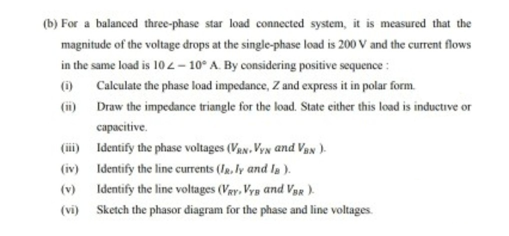
Transcribed Image Text:(b) For a balanced three-phase star load connected system, it is measured that the
magnitude of the voltage drops at the single-phase load is 200 V and the current flows
in the same load is 10 2– 10° A. By considering positive sequence :
(i)
Calculate the phase load impedance, Z and express it in polar form.
(i) Draw the impedance triangle for the load. State either this load is inductive or
capacitive.
(iii) Identify the phase voltages (VaN. VyN and VaN )-
(iv) Identify the line currents (Ig, ly and la ).
(v)
Identify the line voltages (VRy, Vys and VaR ).
(vi)
Sketch the phasor diagram for the phase and line voltages.
Expert Solution
This question has been solved!
Explore an expertly crafted, step-by-step solution for a thorough understanding of key concepts.

This is a popular solution!

Trending now
This is a popular solution!

Step by step
Solved in 3 steps with 3 images

Knowledge Booster


Learn more about
Need a deep-dive on the concept behind this application? Look no further. Learn more about this topic, electrical-engineering and related others by exploring similar questions and additional content below.Recommended textbooks for you
Introductory Circuit Analysis (13th Edition)
Electrical Engineering
ISBN:
9780133923605
Author:
Robert L. Boylestad
Publisher:
PEARSON

Delmar's Standard Textbook Of Electricity
Electrical Engineering
ISBN:
9781337900348
Author:
Stephen L. Herman
Publisher:
Cengage Learning

Programmable Logic Controllers
Electrical Engineering
ISBN:
9780073373843
Author:
Frank D. Petruzella
Publisher:
McGraw-Hill Education
Introductory Circuit Analysis (13th Edition)
Electrical Engineering
ISBN:
9780133923605
Author:
Robert L. Boylestad
Publisher:
PEARSON
Delmar's Standard Textbook Of Electricity
Electrical Engineering
ISBN:
9781337900348
Author:
Stephen L. Herman
Publisher:
Cengage Learning
Programmable Logic Controllers
Electrical Engineering
ISBN:
9780073373843
Author:
Frank D. Petruzella
Publisher:
McGraw-Hill Education

Fundamentals of Electric Circuits
Electrical Engineering
ISBN:
9780078028229
Author:
Charles K Alexander, Matthew Sadiku
Publisher:
McGraw-Hill Education

Electric Circuits. (11th Edition)
Electrical Engineering
ISBN:
9780134746968
Author:
James W. Nilsson, Susan Riedel
Publisher:
PEARSON

Engineering Electromagnetics
Electrical Engineering
ISBN:
9780078028151
Author:
Hayt, William H. (william Hart), Jr, BUCK, John A.
Publisher:
Mcgraw-hill Education,