Beam with cross section area shown in fig (2), the length (L =500 mm), effected by tensile force (F =60 KN), the modulus of elasticity (E =200 GN/m). Determine the elongation in the length of the beam? F h=18mm b=15mm r=6mm h F b Figure (2)
Beam with cross section area shown in fig (2), the length (L =500 mm), effected by tensile force (F =60 KN), the modulus of elasticity (E =200 GN/m). Determine the elongation in the length of the beam? F h=18mm b=15mm r=6mm h F b Figure (2)

Mechanics of Materials (MindTap Course List)
9th Edition
ISBN:9781337093347
Author:Barry J. Goodno, James M. Gere
Publisher:Barry J. Goodno, James M. Gere
Chapter6: Stresses In Beams (advanced Topics)
Section: Chapter Questions
Problem 6.3.12P: The cross section of a bimetallic strip is shown in the figure. Assuming that the moduli of...

Related questions
Question
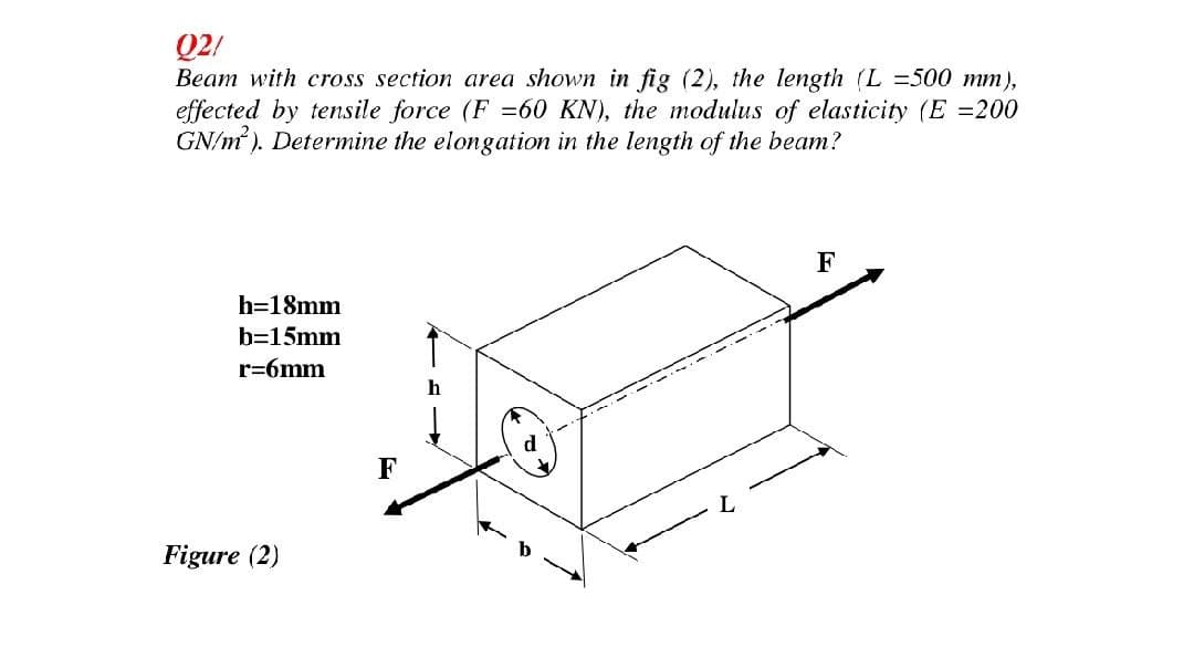
Transcribed Image Text:Q2/
Beam with cross section area shown in fig (2), the length (L =500 mm),
effected by tensile force (F =60 KN), the modulus of elasticity (E =200
GN/m). Determine the elongation in the length of the beam?
F
h=18mm
b=15mm
r=6mm
F
Figure (2)
Expert Solution
This question has been solved!
Explore an expertly crafted, step-by-step solution for a thorough understanding of key concepts.

Step by step
Solved in 3 steps with 3 images

Knowledge Booster


Learn more about
Need a deep-dive on the concept behind this application? Look no further. Learn more about this topic, mechanical-engineering and related others by exploring similar questions and additional content below.Recommended textbooks for you
Mechanics of Materials (MindTap Course List)
Mechanical Engineering
ISBN:
9781337093347
Author:
Barry J. Goodno, James M. Gere
Publisher:
Cengage Learning
Mechanics of Materials (MindTap Course List)
Mechanical Engineering
ISBN:
9781337093347
Author:
Barry J. Goodno, James M. Gere
Publisher:
Cengage Learning