Consider a beam shown in the figure below. (Figure 1) Part A Express the internal shear in the beam as a function of x for 0
Consider a beam shown in the figure below. (Figure 1) Part A Express the internal shear in the beam as a function of x for 0

Mechanics of Materials (MindTap Course List)
9th Edition
ISBN:9781337093347
Author:Barry J. Goodno, James M. Gere
Publisher:Barry J. Goodno, James M. Gere
Chapter6: Stresses In Beams (advanced Topics)
Section: Chapter Questions
Problem 6.3.12P: The cross section of a bimetallic strip is shown in the figure. Assuming that the moduli of...

Related questions
Question
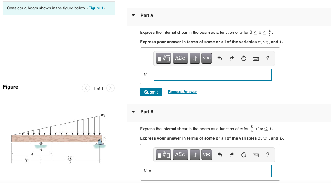
Transcribed Image Text:Consider a beam shown in the figure below. (Figure 1)
Part A
Express the internal shear in the beam as a function of a for 0 < x<.
Express your answer in terms of some or all of the variables x, wo, and L.
Vol AEo vec
V =
Figure
< 1 of 1
Submit
Request Answer
Part B
Express the internal shear in the beam as a function of æ for <x<L.
Express your answer in terms of some or all of the variables x, wo, and L.
πν ΑΣφ
?
vec
V =
v-
Expert Solution
This question has been solved!
Explore an expertly crafted, step-by-step solution for a thorough understanding of key concepts.

This is a popular solution!

Trending now
This is a popular solution!

Step by step
Solved in 2 steps with 2 images

Knowledge Booster


Learn more about
Need a deep-dive on the concept behind this application? Look no further. Learn more about this topic, mechanical-engineering and related others by exploring similar questions and additional content below.Recommended textbooks for you
Mechanics of Materials (MindTap Course List)
Mechanical Engineering
ISBN:
9781337093347
Author:
Barry J. Goodno, James M. Gere
Publisher:
Cengage Learning
Mechanics of Materials (MindTap Course List)
Mechanical Engineering
ISBN:
9781337093347
Author:
Barry J. Goodno, James M. Gere
Publisher:
Cengage Learning