Design a rigid flange coupling to transmit a torque of 257N-m between two coaxial shafts. The shaft is made of alloy steel, flanges out of cast iron and bolts out of steel. Four bolts are used to couple the flanges. The shafts are keyed to the flange hub. The permissible stresses are given below: Shear stress on shaft =100MPa Bearing or crushing stress on shaft =250MPa Shear stress on keys =100MPa Bearing stress on keys = 250MPa Shearing stress on cast iron = 200Mpa Shear stress on bolts =100MPa Answer in Word please
Design a rigid flange coupling to transmit a torque of 257N-m between two coaxial shafts. The shaft is made of alloy steel, flanges out of cast iron and bolts out of steel. Four bolts are used to couple the flanges. The shafts are keyed to the flange hub. The permissible stresses are given below: Shear stress on shaft =100MPa Bearing or crushing stress on shaft =250MPa Shear stress on keys =100MPa Bearing stress on keys = 250MPa Shearing stress on cast iron = 200Mpa Shear stress on bolts =100MPa Answer in Word please

Mechanics of Materials (MindTap Course List)
9th Edition
ISBN:9781337093347
Author:Barry J. Goodno, James M. Gere
Publisher:Barry J. Goodno, James M. Gere
Chapter3: Torsion
Section: Chapter Questions
Problem 3.3.5P: A prospector uses a hand-powered winch (see figure) to raise a bucket of ore in his mine shaft. The...

Related questions

Question
100%
Design a rigid flange coupling to transmit a torque of 257N-m between two coaxial shafts. The shaft
is made of alloy steel, flanges out of cast iron and bolts out of steel. Four bolts are used to couple the
flanges. The shafts are keyed to the flange hub. The permissible stresses are given below:
Shear stress on shaft =100MPa
Bearing or crushing stress on shaft =250MPa
Shear stress on keys =100MPa
Bearing stress on keys = 250MPa
Shearing stress on cast iron = 200Mpa
Shear stress on bolts =100MPa
Answer in Word please
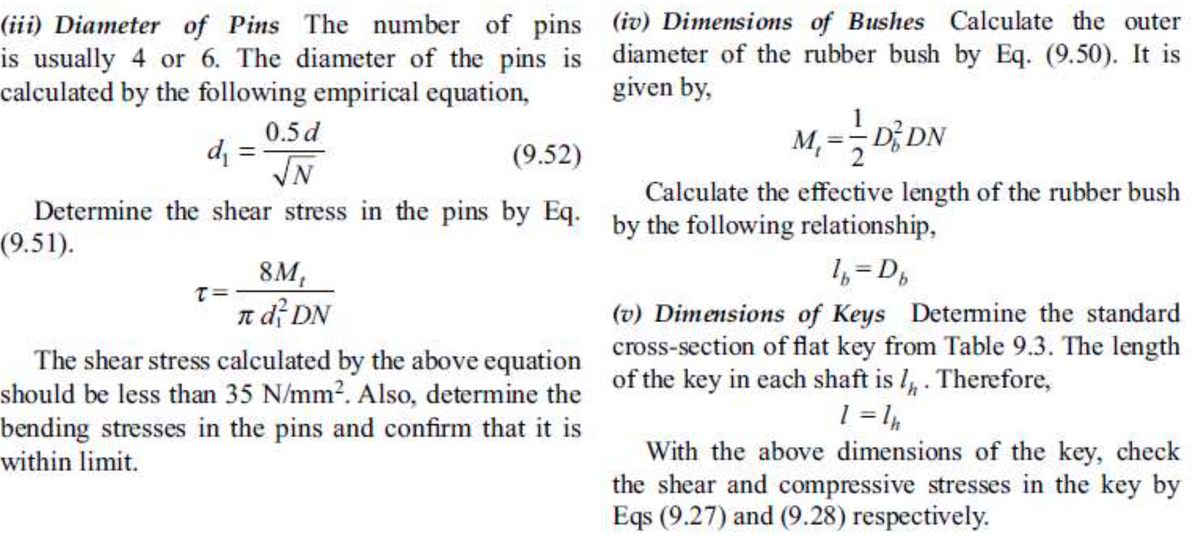
Transcribed Image Text:(iii) Diameter of Pins The number of pins (iv) Dimensions of Bushes Calculate the outer
is usually 4 or 6. The diameter of the pins is diameter of the rubber bush by Eq. (9.50). It is
calculated by the following empirical equation,
given by,
0.5d
%3D
M, =-D; DN
d =
(9.52)
N.
Calculate the effective length of the rubber bush
Determine the shear stress in the pins by Eq. by the following relationship,
(9.51).
8M,
T= -
1, =D,
n df DN
(v) Dimensions of Keys Detemine the standard
The shear stress calculated by the above equation cross-section of flat key from Table 9.3. The length
should be less than 35 N/mm?. Also, determine the of the key in each shaft is I, . Therefore,
bending stresses in the pins and confirm that it is
With the above dimensions of the key, check
the shear and compressive stresses in the key by
Eqs (9.27) and (9.28) respectively.
within limit.
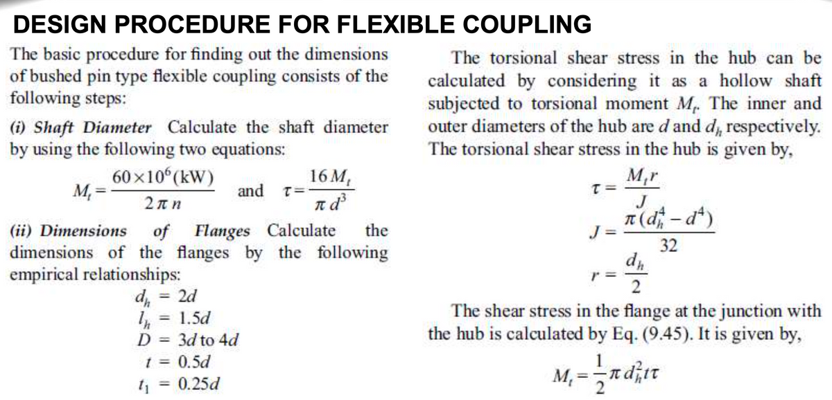
Transcribed Image Text:DESIGN PROCEDURE FOR FLEXIBLE COUPLING
The basic procedure for finding out the dimensions
of bushed pin type flexible coupling consists of the
following steps:
The torsional shear stress in the hub can be
calculated by considering it as a hollow shaft
subjected to torsional moment M. The inner and
outer diameters of the hub are d and d, respectively.
The torsional shear stress in the hub is given by,
(i) Shaft Diameter Calculate the shaft diameter
by using the following two equations:
60x10 (kW)
16 M,
and T=-
M,r
M, =
2πη
J
n(d-dt)
|
(ii) Dimensions
of Flanges Calculate
the
J =
32
dimensions of the flanges by the following
empirical relationships:
2d
%3D
The shear stress in the flange at the junction with
the hub is calculated by Eq. (9.45). It is given by,
1.5d
%3D
D = 3d to 4d
t = 0.5d
%3D
1
%3D
%3D
t = 0.25d
%3D
2
Expert Solution
This question has been solved!
Explore an expertly crafted, step-by-step solution for a thorough understanding of key concepts.

This is a popular solution!

Trending now
This is a popular solution!

Step by step
Solved in 2 steps with 7 images

Knowledge Booster


Learn more about
Need a deep-dive on the concept behind this application? Look no further. Learn more about this topic, mechanical-engineering and related others by exploring similar questions and additional content below.Recommended textbooks for you
Mechanics of Materials (MindTap Course List)
Mechanical Engineering
ISBN:
9781337093347
Author:
Barry J. Goodno, James M. Gere
Publisher:
Cengage Learning
Mechanics of Materials (MindTap Course List)
Mechanical Engineering
ISBN:
9781337093347
Author:
Barry J. Goodno, James M. Gere
Publisher:
Cengage Learning