Design and draw a cast iron flange coupling for a mild steel shaft transmitting 80 kW at rpm with the following specifications: Q1: Allowable shear stress in the shaft = 400 MPa Permissible angle of twist < 1° in a length of 20 diameters Allowable shear stress in the coupling bolts = 30 MPa Rigidity modulus of shaft materials = 85 GPa Allowable shear stress for hub material = 15 MPa You may adopt, width of key = 25 mm, thickness of key = 14 mm You may also consider that the shaft and key are made of the same material. Four number of bolts are to be used in the coupling. Find out the diameter of the shaft required main dimensions of the flanges and the key. Adopt suitable dimensions. Draw a neat sketch for the flange coupling with the designed dimensions.
Design and draw a cast iron flange coupling for a mild steel shaft transmitting 80 kW at rpm with the following specifications: Q1: Allowable shear stress in the shaft = 400 MPa Permissible angle of twist < 1° in a length of 20 diameters Allowable shear stress in the coupling bolts = 30 MPa Rigidity modulus of shaft materials = 85 GPa Allowable shear stress for hub material = 15 MPa You may adopt, width of key = 25 mm, thickness of key = 14 mm You may also consider that the shaft and key are made of the same material. Four number of bolts are to be used in the coupling. Find out the diameter of the shaft required main dimensions of the flanges and the key. Adopt suitable dimensions. Draw a neat sketch for the flange coupling with the designed dimensions.

Mechanics of Materials (MindTap Course List)
9th Edition
ISBN:9781337093347
Author:Barry J. Goodno, James M. Gere
Publisher:Barry J. Goodno, James M. Gere
Chapter2: Axially Loaded Members
Section: Chapter Questions
Problem 2.2.11P: A small lab scale has a rigid L-shaped frame ABC consisting of a horizontal arm AB (length b = 10...

Related questions

Question
Transcribed Image Text:Q1:
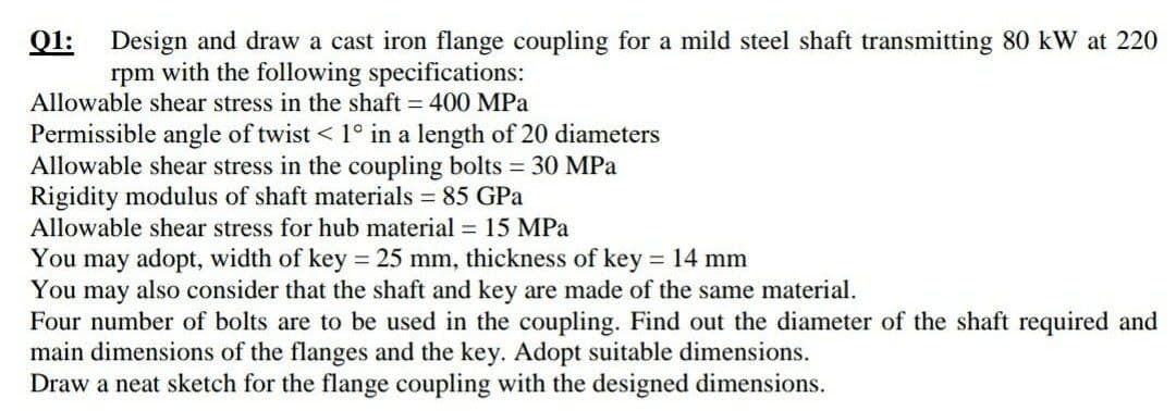
Design and draw a cast iron flange coupling for a mild steel shaft transmitting 80 kW at 220
rpm with the following specifications:
Allowable shear stress in the shaft = 400 MPa
Permissible angle of twist < 1° in a length of 20 diameters
Allowable shear stress in the coupling bolts 30 MPa
Rigidity modulus of shaft materials = 85 GPa
Allowable shear stress for hub material = 15 MPa
You may adopt, width of key = 25 mm, thickness of key = 14 mm
You may also consider that the shaft and key are made of the same material.
Four number of bolts are to be used in the coupling. Find out the diameter of the shaft required and
main dimensions of the flanges and the key. Adopt suitable dimensions.
Draw a neat sketch for the flange coupling with the designed dimensions.
Expert Solution
This question has been solved!
Explore an expertly crafted, step-by-step solution for a thorough understanding of key concepts.

Step by step
Solved in 3 steps

Knowledge Booster


Learn more about
Need a deep-dive on the concept behind this application? Look no further. Learn more about this topic, mechanical-engineering and related others by exploring similar questions and additional content below.Recommended textbooks for you
Mechanics of Materials (MindTap Course List)
Mechanical Engineering
ISBN:
9781337093347
Author:
Barry J. Goodno, James M. Gere
Publisher:
Cengage Learning
Mechanics of Materials (MindTap Course List)
Mechanical Engineering
ISBN:
9781337093347
Author:
Barry J. Goodno, James M. Gere
Publisher:
Cengage Learning