Determine the maximum forward current and the maximum reverse voltage for the diodes IN4001, IN34, and IN5231B using the datasheets attached.
Determine the maximum forward current and the maximum reverse voltage for the diodes IN4001, IN34, and IN5231B using the datasheets attached.

Chapter59: Motor Startup And Troubleshooting Basics
Section: Chapter Questions
Problem 12SQ: How is a solid-state diode tested? Explain.

Related questions
Question
Transcribed Image Text:þetermine the maximum forward current and the maximum reverse voltage for the diodes IN4001,
IN34, and IN5231B using the datasheets attached.
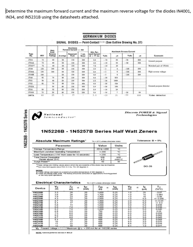
GERMANIUM DIODES
SIGNAL DIODES – Peint-Contact ) (See Outine Drawing No. 37)
Hasimum
Farward Curent-me
Max.
Cant
Revene
Valtge
Nanimum Revene Cumet
Mi For
ward Curne
+IV me
Tyae
Regarent
Peak
PRV
Avemge
Surge
Valt
Velt
Comments
IN4
1
5.0
-10
Genl perpo
INA
60
Se
190
30
INSsle
15e
-10
30
Matched pair of INHA
INM
100
150
30
S00
High re vatag
INSMA
150
40
-3
150
40
RENI
IN4
40
833
INSI
IN
Se
40
100
300
25
160
150
400
40
INS2A
150
400
100
General purpon detecter
INS4
35
10
INSA
INTA
25
15
5.0
-10
-50
video detector
35
Discrete POWER & Signal
Technologies
National
Semiconductor
1N5226B
1N5257B Series Half Watt Zeners
Absolute Maximum Ratings
Tolerance: B- 5%
TA-ruess erwe note
Parameter
Value
Units
65 00
Srage Temoerature Range
Maim Juncion Operng Tevperatre
Lead Temperature (1/16" trom cone for 10 seconda)
Tata DeviceDesipeton
Derale e S
Surge Power
230
S00
40
10
wwing
aty ore may ep
DO-35
based onamamun
eng ped
Electrical Characteristics
TA-
omere noe
Zz
VR
(V)
Te
IR
Device
(mA
33
20
24
23
22
19
20
20
20
20
20
1,600
1,700
1.900
2,000
1.900
1,000
1,600
1,600
1.000
750
500
500
600
800
1.0
1.0
1.0
1.0
2.0
2.0
3.0
3.5
4.0
5.0
26
15
10
5.0
0.07
025
0.25
025
0.25
035
0.25
0.25
0.25
0.25
0.25
025
IN2278
1NS22
3.6
3.9
43
4.7
5.1
5.6
-0.06
0.050
0.03
0.3
0.030
0038
0.045
5.0
5.0
5.0
5.0
3.0
3.0
3.0
3.0
3.0
3.0
1N2310
1
70
70
62
IN
1N52378
75
8.0
6.5
8.7
8.1
0.0e2
O 065
0.25
6.5
7.0
6.0
8.4
9.1
10
025
0.25
0.25
0.075
INS418
11
22
600
600
2.0
1.0
025
V, Fownd Voltege-1.1 V Maimuma L-200 mA for a 1NS200 eries
O077
NGTE Nationa preterred evices in BOLD
as
aaasa alaalaalalal
eseanan
1N5226B - 1N5257B Series
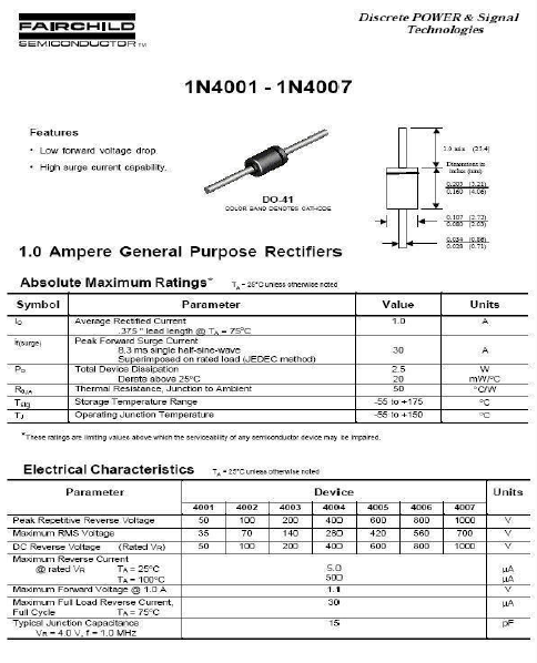
Transcribed Image Text:FAIRCHILD
Discrete POWER & Signal
Technologies
SEMICONDUCTOR ru
1N4001 - 1N4007
Features
• Low torward voltage drop.
10 a14
* High aurge eurrent cepablity.
0.160 4.06)
DO 41
COLOR BAND DGNOTEs CAT-Cos
1.0 Ampere General Purpose Rectifiers
Absolute Maximum Ratings
T-26*Cuness atnerwioe rated
Symbol
Parameter
Value
Units
Average Recttied Current
1.0
375" lead length a TA - 75°C
Tsargei
Peak Forward Surge Current
8.3 ms single halr-sine-wave
Superimposed on rated load JEDEC method)
30
A
Pa
Total Device Dissipetion
2.5
20
Derste above 25°C
Ra
Tag
Thermal Resistence, Junction to Amblent
5D
Storage Temperature Range
55 to +175
-55 to +150
Operating Junetion Temperature
PC
"These rarings are imithg valuee above whien the serviceatity or any semiconductor device may te impaired.
Electrical Characteristics
T-20'Cunieas ofherwise roted
Parameter
Device
Units
4001
4002
4003
4004
4005
4006
4007
Peak Repetitive Reverse Vellage
Maximum RME votage
DC Reverse Voltage
Maximum Reverse Current
@ rated VR
50
100
200
400
600
80
1000
V.
35
70
140
280
420
560
700
(Rated VR)
50
800
100
200
4D0
60D0
1C00
TA = 20°C
TA- 100°C
S.0
500
1.1
HA
HA
Maximum Forward Voitnge 1.0 A
Maximum Ful Load Reverse Current,
Full Cycle
Typical Juneton Capacitance
Vn-4.0 V, t-1,0 MHz
30
TA= 75°C
15
Expert Solution
This question has been solved!
Explore an expertly crafted, step-by-step solution for a thorough understanding of key concepts.

Step by step
Solved in 2 steps

Knowledge Booster


Learn more about
Need a deep-dive on the concept behind this application? Look no further. Learn more about this topic, electrical-engineering and related others by exploring similar questions and additional content below.Recommended textbooks for you

Electricity for Refrigeration, Heating, and Air C…
Mechanical Engineering
ISBN:
9781337399128
Author:
Russell E. Smith
Publisher:
Cengage Learning

Delmar's Standard Textbook Of Electricity
Electrical Engineering
ISBN:
9781337900348
Author:
Stephen L. Herman
Publisher:
Cengage Learning
Electricity for Refrigeration, Heating, and Air C…
Mechanical Engineering
ISBN:
9781337399128
Author:
Russell E. Smith
Publisher:
Cengage Learning
Delmar's Standard Textbook Of Electricity
Electrical Engineering
ISBN:
9781337900348
Author:
Stephen L. Herman
Publisher:
Cengage Learning