Determine the maximum uniform distributed load w that can be applied to the W12 x 14 beam shown below if the maximum allowable bending stress is Oallow = 24 ksi and the maximum allowable shear is Tallow = 10.0 ksi. The distance between the supports is 20 ft. (Figure 3)
Determine the maximum uniform distributed load w that can be applied to the W12 x 14 beam shown below if the maximum allowable bending stress is Oallow = 24 ksi and the maximum allowable shear is Tallow = 10.0 ksi. The distance between the supports is 20 ft. (Figure 3)

Chapter2: Loads On Structures
Section: Chapter Questions
Problem 1P

Related questions

Question
100%
Solve part C please and circle final answer units must be in lb/ft
Transcribed Image Text:To know how to use shear and bending-moment diagrams to
determine the design requirements of a steel beam used to
support a loading.
I Review
When designing a steel beam to support a given loading,
engineers often use bending characteristics as the primary
criterion; shear characteristics are then taken into account, and, if
multiple available designs are still viable, weight and cost are then
considered to complete the specification.
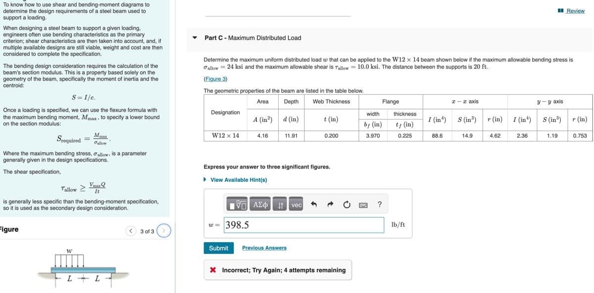
Part C - Maximum Distributed Load
Determine the maximum uniform distributed load w that can be applied to the W12 x 14 beam shown below if the maximum allowable bending stress is
Oallow = 24 ksi and the maximum allowable shear is Tallow = 10.0 ksi. The distance between the supports is 20 ft.
The bending design consideration requires the calculation of the
beam's section modulus. This is a property based solely on the
geometry of the beam, specifically the moment of inertia and the
centroid:
(Figure 3)
The geometric properties of the beam are listed in the table below.
S= I/c.
Area
Depth
Web Thickness
Flange
I-z axis
y-y axis
Once a loading is specified, we can use the flexure formula with
the maximum bending moment, Mmax, to specify a lower bound
on the section modulus:
Designation
width
thickness
A (in²)
d (in)
t (in)
I (in*)
S(in*)
r (in) I (in*)
S (in)
r (in)
by (in)
t; (in)
Mmax
W12 x 14
4.16
11.91
0.200
3.970
0.225
88.6
14.9
4.62
2.36
1.19
0.753
Srequired =
Oallow
Where the maximum bending stress, oallow, is a parameter
generally given in the design specifications.
Express your answer to three significant figures.
The shear specification,
• View Available Hint(s)
Vmar Q
Tallow 2
It
is generally less specific than the bending-moment specification,
so it is used as the secondary design consideration.
ν ΑΣφ ve
?
w = 398.5
lb/ft
Figure
< 3 of 3
Submit
Previous Answers
X Incorrect; Try Again; 4 attempts remaining
-L + L -
Expert Solution
This question has been solved!
Explore an expertly crafted, step-by-step solution for a thorough understanding of key concepts.

This is a popular solution!

Trending now
This is a popular solution!

Step by step
Solved in 6 steps with 6 images

Knowledge Booster


Learn more about
Need a deep-dive on the concept behind this application? Look no further. Learn more about this topic, civil-engineering and related others by exploring similar questions and additional content below.Recommended textbooks for you

Structural Analysis (10th Edition)
Civil Engineering
ISBN:
9780134610672
Author:
Russell C. Hibbeler
Publisher:
PEARSON

Principles of Foundation Engineering (MindTap Cou…
Civil Engineering
ISBN:
9781337705028
Author:
Braja M. Das, Nagaratnam Sivakugan
Publisher:
Cengage Learning
Structural Analysis (10th Edition)
Civil Engineering
ISBN:
9780134610672
Author:
Russell C. Hibbeler
Publisher:
PEARSON
Principles of Foundation Engineering (MindTap Cou…
Civil Engineering
ISBN:
9781337705028
Author:
Braja M. Das, Nagaratnam Sivakugan
Publisher:
Cengage Learning

Fundamentals of Structural Analysis
Civil Engineering
ISBN:
9780073398006
Author:
Kenneth M. Leet Emeritus, Chia-Ming Uang, Joel Lanning
Publisher:
McGraw-Hill Education


Traffic and Highway Engineering
Civil Engineering
ISBN:
9781305156241
Author:
Garber, Nicholas J.
Publisher:
Cengage Learning