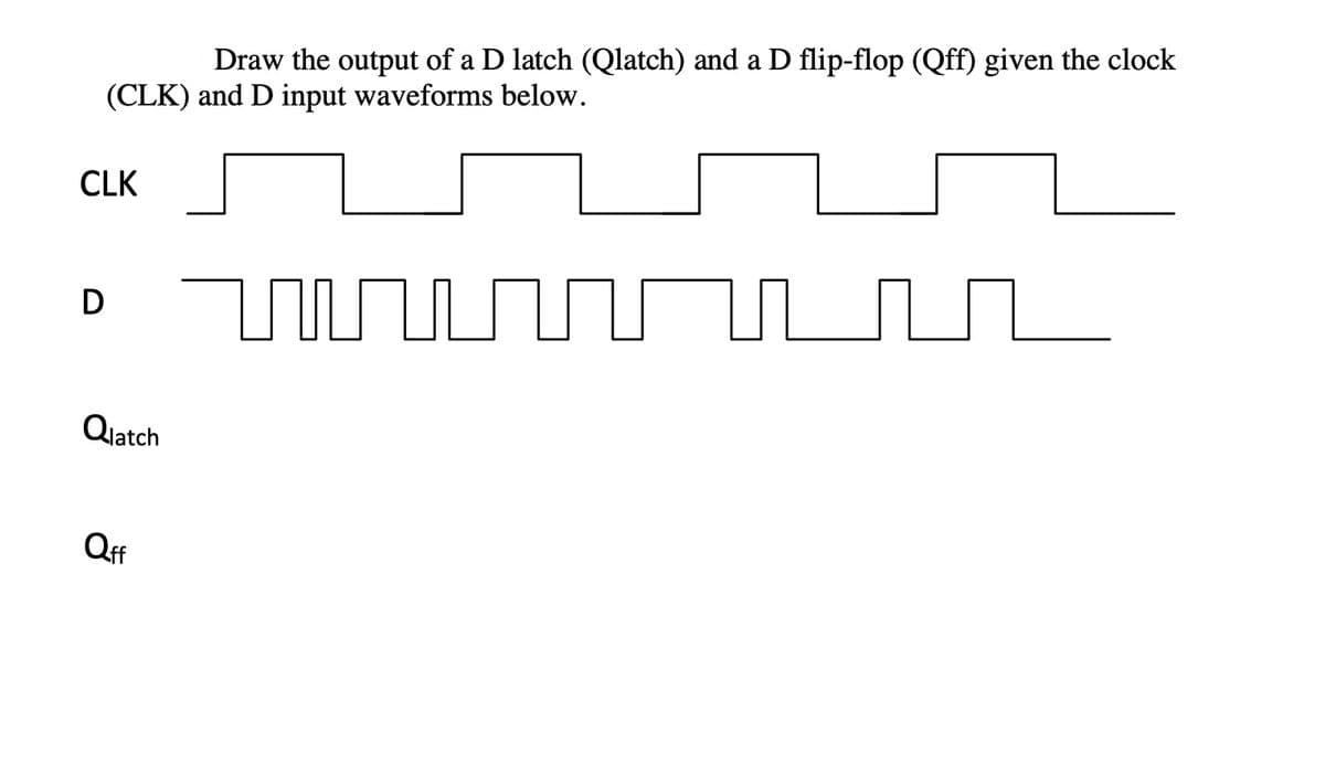
Draw the output of a D latch (Qlatch) and a D flip-flop (Qff) given the clock (CLK) and D input waveforms below. LK Ratch


Q: 7. Two edge-triggered J-K flip-flops are shown in below Figure. If the inputs are as shown, draw the…
A:
Q: Figure Q2(a) is the state diagram for a digital system. Construct a Finite State Machine circuit…
A:
Q: Determine the Q and Q' output waveforms of the D flip-flop with D and CLK inputs are given in figure…
A: Digital circuits can either be combinational circuits or sequential circuits. Sequential circuits…
Q: i for the D and CLK inputs in Figure Determine the Q that the positive edge-triggered flip-flop is…
A: Latch is asynchronous device. It is level triggered device. It check input and change output…
Q: 9 Two edge-triggered J-K flip-flops are shown in The Figure. If the inputs are as shown, draw the Q…
A:
Q: Q2) a- For the below waveforms. Draw the ( Set and Reset) inputs. Assume the (S-R) flip-flop have a…
A: According to the question, for the waveform shown below We need to draw the input for SR flip flop.…
Q: en the mput umng diagram oI шe mриts к and S, det ne the Q Tor al active-lOW input SR latch and…
A:
Q: 9 Using D flip-flops, (a) Design a counter with the following repeated binary sequence: 0, 1, 2, 4,…
A: Since we only answer up to 3 sub-parts, we’ll answer the first 3. Please resubmit the question and…
Q: Draw the timing diagram lines below for the Q output of a D Latch and the Q output of a D Flip-Flop.…
A: Latch are Level Triggered and Flip flop are Edge sensitive. When a circuit is edge triggered the…
Q: output for the inputs in figure below Assume that Q starts LOW. 1) If the J-K flip-flop is positive…
A:
Q: A pattern detector which gives 1 at its 1-bit output when the last four values of its 1-bit input…
A: We are authorized to answer three subparts at a time, since you have not mentioned which part you…
Q: Discussion: what is the effect the activating the (preset and clear) on the output state for J-K…
A: Preset and Clear are the two asynchronous inputs are provided to all flip-flops to make the output…
Q: Draw a circuit for an asynchronous counter (using JK flip-flops and gates) that counts from decimal…
A: consider the given circuit:
Q: Assume that initially in Figure P9.7. Determine the values of A and B after one Clk pulse. Note that…
A:
Q: 5. Explain the working of Master-Slave D Flip-Flop What is the basic usage of Flip-flops Y D D D D…
A:
Q: - Develop a truth table of the following latch: PRE S Q EN R CLR -How to convert a JK flip flop into…
A:
Q: 22 - What does the letter "X" letter in flip-flop transition tables? O A LOW level O B) Crass s tate…
A: x generally means don't care terms in transition table of jk flip flop
Q: Question 3. Consider the JK- flip flop given below. J Q CLK K Fill in the below state table for the…
A:
Q: Design a Up Down Counter by using JK flip flop and verify the output of your designed circuit on any…
A: 3 bit up / down Counter, X is mode it denotes whether the counter is up/ down. X=1 =>up counter…
Q: (a) Provide a block diagram and a function table for the D-type flip-flop with falling edge…
A: Since you have posted multiple questions, we will solve the first question for you. If you require…
Q: Q2: Simplify A PN flip -flop has four operations. clear to zero. no change. complement. and set to…
A: Consider the given data: Here, PN flip-flop operations are, “Clear to 0” for the inputs PN=00 “No…
Q: Draw the output waveform for D flip flop the inputs shown in the timing diagram below Clock: Dinput:
A: To find the output
Q: 2- Draw the output waveform for D flip flop the inputs shown in the timing diagram below Clock…
A: A D flip flop (DFF) has two input signals and an output signal, Q. Clock and D are the input…
Q: 2- Design Asynchronous counter using positive edge J-K flip flop to count the following states…
A: According to the desirable counter sequence, the Truth table will be Output waveform w.r.t clock…
Q: 5. A timing diagram below shows a D Flip-flop and the input clock. Show the transition of the output…
A: Writing the characteristic table of D-FF. DQnQn+1000010101111 It could be concluded from the…
Q: Design a counter which simultaneously satisfies all of the following requirements: • Have no input •…
A: We need to design a counter circuit for the given state diagram :…
Q: 7−bit shift register using JK flip-flops
A: Shift Register It is a type of sequential logic circuit that can be used for the storage and…
Q: Design a Asynchronous Up counter that start it’s counting from zero and ends at 13 and again starts…
A: The counter should count up to 13, It is a MOD-13 Counter log2(13) = 3.7 Hence it required 4 flip…
Q: Discussion: what is the effect the activating the (preset and clear) on the output state for J-K…
A: a) Effect of activating the (present and clear) on the output state for J-K flip flop The…
Q: 4- Draw the output waveform if the signal shown in Figure below is applied to inputs of J-K…
A: The behavior of a JK flipflop with active-low preset and clear inputs can be described as, The…
Q: 1- Design synchronous counter using negative edge D- type flip flop to count the following states :…
A:
Q: Determine the Q output waveforms of the flip-flop in Figure i for the D and CLK inputs in Figure…
A: Latch is asynchronous device. It is level triggered device. It check input and change output…
Q: Draw state diagram of J-K flip flop 1 Add file Write Verilog code of J-K flip flop 1 Add file
A:
Q: triggered flip-flop) for: (a) T flip-flop with active low clear (CLR') and preset (PRE') (b) T…
A:
Q: D Q X D CLK
A:
Q: 5. If the flip-flop is set, what are the output states of the master and slave when a high is…
A: The given circuit diagram is
Q: show the waveforms for each flip-flop output with respect For the ring counter in Figure to the…
A: Truth table of the given ring counter Clock pulse Q0 Q1 Q2 Q3 Q4 Q5 Q6 Q7 Q8 Q9 0 1 0 0 0 0 0…
Q: 4- Draw the output waveform if the signal shown in Figure below is applied to inputs of J-K…
A: Latch is asynchronous device. It is level triggered device. It check input and change output…
Q: Design synchronous counter using negative edge D- type flip flop to count the following states : ( 4…
A:
Q: Q1: For the J-K flip-flop, determine the Q output for the inputs in figure below Assume that Q…
A:
Q: Complete the timing diagram for a J-K flip-flop with a falling-edge trigger and asynchronous ClrN…
A:
Q: 5. Explain the working of Master-Slave D Flip-Flop . What is the basic usage of Flip-flops Y D D D D…
A:
Q: Assume the output is initially HIGH on a leading edge triggered J-K flip flop. For the inputs shown,…
A: According to the question we have to discuss about the pulse on which output go from high to low.
Q: Design synchronous counter using negative edge D- type flip flop to count the following states : (4…
A: "Since you have asked multiple questions, we will solve the first question for you. If you want any…
Q: Explain the set and clear functions on the JK Flip-flop!
A:
Q: 1. Design a 4-bit synchronous down-counter using T flip-flops. i. Write a "function table" showing…
A:
Q: 3. The waveforms shown in Figure below are applied to a negative edge-triggered JK flip- flop. The…
A: In this question, We need to draw the output waveform of the jK filp flop. We know the output of…
Q: Draw your manually drawn synchronous counter's (utilizing D Flip-Flops) outputs' waveform te the…
A: The output waveform for the above circuit diagram can be drawn by referring to the following truth…
Q: Determine the output Q for the given J-K flip flop and the waveforms. HIGH PRE J. CLR E LL FFL CL…
A:


Trending now
This is a popular solution!

Step by step
Solved in 2 steps with 2 images


- Flip-flops Give the disadvantages and advantages of Positive Edge Triggering vs Negative Edge Trigerring. Then, give an example of digital circuit and explain where a) Positive Edge is used and b) Negative edge is usedDesign a 4 bit binary ripple counter that trigger as mention below on the edge of the clock. What will be the count if (a) the normal outputs of the flip‐flops are connected to the clock and that trigger on the positive‐edge of the clock (b) the complement outputs of the flip‐flops are connected to the clock and that trigger on the negative‐edge of the clockDesign a synchronous 3-bit binary up-counter using D flip-flops.Determine the Number of FFs required, Counting Range, and Drow theexcitation table
- Sketch the (Preset,Clear,K) for the given waveform. Assume the flip-flop raising edge triggering clook. Paying attention to the output wave Q given in the questionDraw and explain the operation in detail (while including necessary table) the block diagram and logic circuit diagram of J-K master-slave (M-S) flip flop. Why an M-S configuration is necessary?Design a binary counter that counts from 0 to 5. At each clock pulse, 3 lights will be ON and 3 lights will be OFF. Use JK flip flops.Steps for solution:-> State diagram-> State table-> K-map reductions-> design
- Draw the logic diagram of a four-bit binary ripple countdown counter using:1. flip-flops that trigger on the positive-edge of the clock; and2. flip-flops that trigger on the negative-edge of the clock.1)For the state diagram given below, create the state table and design the sequential circuit with SR type Flip Flop and draw the logic diagrams. Note: States A and B, input X, output YDesign a 2-bit binary counter using: One SR and one JK flip flop.
- 1) Construct a JK flip-flop using a D Flip-flop, a 2-to-1 line multiplexer and an inverter. I need only diagram.A binary ripple counter uses flip‐flops that trigger on the positive edge of the clock. What will be the count if (a) the normal outputs of the flip‐flops are connected to the clock? (b) the complement outputs of the flip‐flops are connected to the clock?(i) Determine how many flip flops are required to build a binary counter that count from 0 to 1023?(ii) Determine the frequency at the output of the last flip flop of this counter for an input clock frequency of 2 MHz.(iii) Give the MOD number of this counter.(iv) If the counter is initially at zero, determine the count if it hold after 2060 pulses.