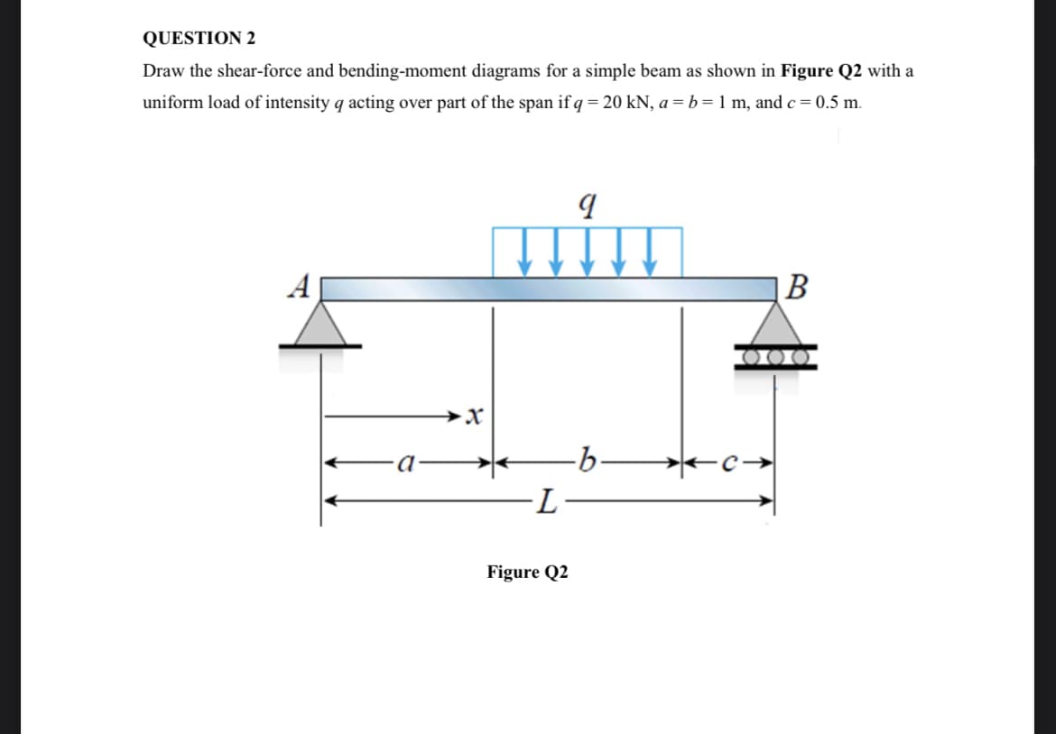
Draw the shear-force and bending-moment diagrams for a simple beam as shown in Figure Q2 with a uniform load of intensity q acting over part of the span if q = 20 kN, a = b= 1 m, and c= 0.5 m. A В Figure Q2
Q: Solve,
A: Uniform distributed load is acting for the distance "4m".load P=(20 kN/m)×4m=80 kN ;this load will…
Q: Determine the fixed-end moments (MA andMB) and fixed-end forces (RA and RB) for a beam oflength L…
A: given; lets take reaction force at A=RAlets take reaction force at B=RBweight density=q0AB=LAC=CB=L2…
Q: The simple beam AB, shown below, supports a concentrated load of 22 kN and a segment of a…
A:
Q: Q1 For the beam shown in figure below, draw the shearing force and bending moment diagrams showing…
A:
Q: 2) Draw shear force and bending moment diagrams of the beam and find the maximum values of the shear…
A: Shear force calculations: ∑V=0 RA+5×6+20=0RA=-30-20RA=-50kNRA=50kN upwards Bending Moment…
Q: A beam of 8 m long, loaded with uniformly distributed load on the 4 m span CE with a concentrated…
A: The free body diagram of the beam is as follows: Calculate the moment about point d as follows:…
Q: 6 kN 15 kN/m 20 kN·m -2 m+1 - B - 3 m- +1 m -2 m-
A: Let us draw SFD and BMD of given loading.
Q: The cantilever beam in Fig. (a) carries a triangular load, the intensity of which varies from zero…
A:
Q: Draw the shear-force and bending-momentdiagrams for a cantilever beam AB carrying a uniformload of…
A:
Q: Draw the Shear Force Diagram (SFD) and Bending Moment Diagram (BMD) for a loaded simply supported…
A:
Q: Draw the free body diagram, shear force diagram, and bending moment diagram for section BC and AB of…
A: Drawing for section Bc,
Q: 1. A cantilever beam supporting two concentrated loads at points A and B, is shown in Figure 1.…
A:
Q: Abeam with a rectangular cross section is simply supported and loaded at its center with a force P.…
A:
Q: Calculate the shear force V and bending moment M at a cross-section located 0.5 m from the fixed…
A: Given data To determine the shear force and bending moment at a distance of 0.5 m from the fixed…
Q: Q. 1. A simply supported wood bam AB with span length L=4 m carries a uniform load of intensity o =…
A:
Q: Draw the complete shearing force and bending moment diagrams for the beam shown in figure Fig.-1.…
A:
Q: P3 (kN) P4 (kN) B 30 kN A L3 (m) L4 (m)
A: Solution: Reactions and B and C can be found using static equilibrium conditions, therefore,…
Q: Draw the Shear force diagram & Bending moment diagram for the cantilever beam as shown in figure,…
A: Taking resolution of vertical forces, RA=10+60+30+10RA=110 N Bending Moment at A,…
Q: Calculate the shear force and bending moment for the beam subjected to the loads as shown in the…
A:
Q: Draw the shear force diagram and bending moment diagram for the loaded cantilever beam as shown in…
A:
Q: For the simply supported beam shown in the figure, write equations for the shearing force and…
A:
Q: Q: For the loaded simply supported beam shown in figure below, if the allowable bending stress is…
A:
Q: For the beam shown, find the reactions at the supports and plot the shear-force and bending-moment…
A:
Q: The simply supported beam is subjected to the loading and has cross-sectional area as in the figure…
A: Draw a free-body diagram of a given beam. Apply force equilibrium in a vertical direction.…
Q: aw the Normal Force Diagram. (b) Draw the shear force diagram. (c) Draw the bending moment…
A:
Q: Q2 (a) The uniformly loaded beam ABC has simple supports at A and B and an overhang BC (see Figure…
A:
Q: А C 2а
A:
Q: H.W Draw shear force digam and bending moment digram for the following beam 300 N 500 N 800 N to 0.5…
A: Given: The load is 300 N, 500 N, and 800 N. The distance from point A is 0.5 m, 1.2 m, and 2 m.
Q: 80 kN/m B 2 m -2 m-
A:
Q: The simple beam AB shown in the figure is subjected to a concentrated load P and a clockwise couple…
A: Given data as per the question The moment applied = PL/3 The load applied on beam =P
Q: 3. For the beam shown below, let wo = 90 N/m and w1 50 N/m. %D Wo | A B -2 m-2 m+3 m 3 m- -2 m…
A:
Q: Draw the shear-force and bending-momentdiagrams for beam AB with a sliding support at Aand an…
A: Shear force is the algebraic sum of the vertical forces at any segment of a beam to the right or…
Q: Question 1: In the system shown in the figure, built-in support at point A, fixed support at point B…
A:
Q: A continuous beam ABC wit h two unequal spans, one of length L and one of length 2L, supports a…
A: Indeterminate system An indeterminate system in the one where Number of unknowns are less than the…
Q: Q2(a) A simple beam is shown in Figure Q2(a) has three concentrated loads at the position indicated.…
A:
Q: Draw the Shear Force Diagram (SFD) and Bending Moment Diagram (BMD) for a loaded simply supported…
A:
Q: 25. A fiberglass pipe is lifted by a sling, as shown in the figure. The outer diameter of the pipe…
A: Given data as per questionLength of pipe =10 ms=4 md2=100 mmd1=100−12=88 mmweight density =1500…
Q: A cantilever beam of length 2 m carries the point loads as shown in Fig 2. Draw the shear force and…
A:
Q: 1. Draw the shear and moment diagrams for the simply supported beam described in the Figure below 8…
A:
Q: Q2(a) A simple beam is shown in Figure Q2(a) has three concentrated loads at the position indicated.…
A: Given data diameter of beam (d) = 200 mm To determine (a) support reactions (b) Maximum…
Q: points A, B and D, respectively, as shown in the figure. A uniformly distributed loac of 4 kN/m…
A:
Q: SKN | SKN A simply supported beam subjected to three point loads as shown in the Figure . Draw shear…
A:
Q: Analyze the simply supported beam shown in figure-6, by drawing its Shear Force and Bending Moment…
A:
Q: The simple beam AB shown in the figure is subjected to a concentrated load P and a clockwise couple…
A: Shear force is defined as the algebraic sum of all vertical forces acting on a segment from the left…
Q: 1. A simply supported beam with rectangular cross-section is loaded as shown in the figure. Draw the…
A:
Q: Draw the shear force diagram (SFD) and bending moment diagram (BMD) for the beam shown in figure. 2…
A:
Q: Q4\ Draw the shear-force and bending-moment diagrams for a beam shown below 3000 N/m В A tosm-l -0.8…
A:
Q: Draw shear force digam and bending moment digram for the following beam 300 N 500 N 800 N to A B 0.5…
A: The given loading system is a cantilever beam loading. Shear force is the force which makes the…
Q: The beam in Figure 1; (a) Draw the Normal Force Diagram. (b) Draw the shear force diagram. (c)…
A:
Step by step
Solved in 2 steps with 2 images
- Find expressions for shear force V and moment M at v = L/2 of beam AB in structure (a). Express V and M in terms of peak load intensity q0and beam length variable L. Repeat for structure (b) but find Fand M at m id-span of member BC.Cantilever beam AB carries an upward uniform load of intensity q1from x = 0 to L/2 (see Fig. a) and a downward uniform load of intensity q from x = L/2 to L. Find q1in terms of q if the resulting moment at A is zero. Draw V and M diagrams for the case of both q and qtas applied loadings. Repeat part (a) for the case of an upward triangularly distributed load with peak intensity q0(see Fig. b). For part (b), find q0, instead of q1The hollow box beam shown in the figure is subjected to a bending moment M of such magnitude that the flanges yield but the webs remain linearly elastic. (a) Calculate the magnitude of the moment M if the dimensions of the cross section are A = 15 in., A] = 12.75 in., h = 9 in., and ey =7.5 in. Also, the yield stress is eY = 33 ksi. (b) What percent of the moment M is produced by the elastic core?
- The cross section of an unbalanced wide-flange beam is shown in the figure. Derive the following formula for the distance /h from the centerline of one flange to the shear center S: h1t2b23ht1b13+t2b23 Also, check the formula for the special cases of a T-beam (b2= t2=0) and a balanced wide-flange beam (t2= ttand b2= ty).A beam supporting a uniform load of intensity q throughout its length rests on pistons at points A, C and B (sec figure). The cylinders are filled with oil and are connected by a tube so that the oil pressure on each piston is the same. The pistons at A and B have diameter d1and the piston at C has diameter D2. (a) Determine the ratio of d2to d1so that the largest bending moment in the beam is as small as possible. Under these optimum conditions, what is the largest bending moment Mmaxin the beam? What is the difference in elevation between point C and the end supports?The beam ABC shown in the figure is simply supported at A and B and has an overhang from B to C. The loads consist of a horizontal force P1= 4,0 kN acting at the end of a vertical arm and a vertical force P2= 8.0 kN acting at the end of the overhang, Determine the shear force Fand bending moment M at a cross section located 3,0 m from the left-hand support. Note: Disregard the widths of the beam and vertical arm and use centerline dimensions when making calculations, Find the value of load A that results in V = 0 at a cross section located 2.0 m from the left-hand support. If P2= 8.0 kN, find the value of load P1that results in M = 0 at a cross section located 2,0 m from the left-hand support.
- Find expressions for shear force V and moment M at mid-span of beam AB in terms of peak load intensity q0and beam length variables a and L Let a = 5L/b.Draw the shear-force and bending-moment diagrams for a cantilever beam AB acted upon by two different load cases. A distributed load with linear variation and maximum intensity q0(see figure part a). A distributed load with parabolic variation and maximum intensity q0(see figure part b).-1 through 5.10-6 A wide-flange beam (see figure) is subjected to a shear force V. Using the dimensions of the cross section, calculate the moment of inertia and then determine the following quantities: The maximum shear stress tinixin the web. The minimum shear stress rmin in the web. The average shear stress t (obtained by dividing the shear force by the area of the web) and the ratio tmax/taver. The shear force Vweb/V carried in the web and the Vweb/V. Note: Disregard the fillets at the junctions of the web and flanges and determine all quantities, including the moment of inertia, by considering the cross section to consist of three rectangles. 5.10-1 Dimensions of cross section: b = 6 in,, ï = 0.5 in., h = 12 in,, A, = 10.5 in., and V = 30 k.
- (a) A simple beam AB with length L and height h supports a uniform load of intensity q (see the figure part a). Obtain a formula for the curvature shortening A of this beam. Also, obtain a formula for the maximum bending stress b in the beam due to the load q. Now assume that the ends of the beam are pinned so that curvature shortening is prevented and a horizontal force H develops at the supports (see the figure part b). Obtain a formula for the corresponding axial tensile stress t . Using the formulas obtained in parts (a) and (b), calculate the curvature shortening , the maximum bending stress b, and the tensile stress t for the following steel beam: length L = 3m, height h = 300 mm, modulus of elasticity E = 200 GPa, and moment of inertia I = 36 x 106 mm4. Also, the load on the beam has intensity q = 25 kN/m. Compare the tensile stress tproduced by the axial forces with the maximum bending stress bproduced by the uniform load.A cantilever beam AB having rectangular cross sections with varying width bxand varying height hxis subjected to a uniform load of intensity q (sec figure). If the width varies linearly with x according to the equation hx= bBxiL^ how should the height hxvary as a function of v in order to have a fully stressed beam? (Express hxin terms of the height hBat the fixed end of the beam.)A propped cantilever beam is subjected to two triangularly distributed loads, each with a peak load intensity equal to q0(see figure), lind the expressions for reactions at A and C using superposition. Plot shear and moment diagrams.