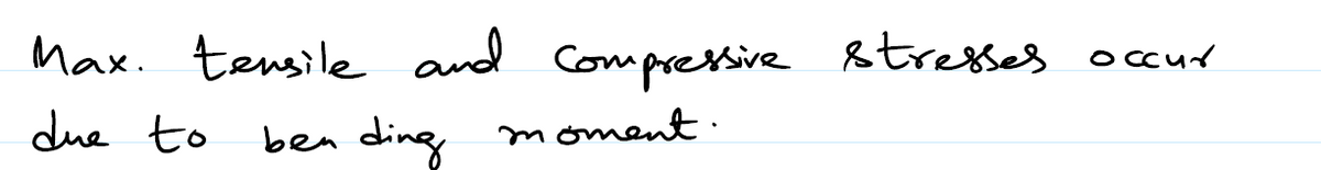
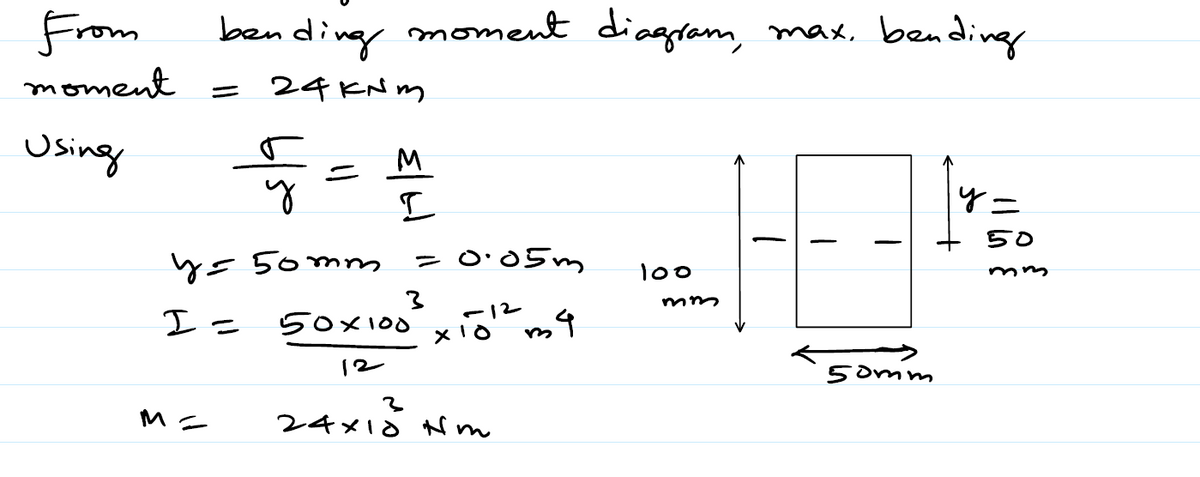
Example (5.3): Find the maximum tensile and compressive stresses for the beam shown in Figure (5.6). 10 KN 2 kN/m 100 mm 50 mm S.E.D (KN) Solution: -10 -14 BM.D(KN.m) -24 Figure (56)


Q: A column with a wide-flange section has a flange width b = 250 mm , height h = 250 m m, web…
A: Given dataWIdth of the flange w = 250mmHeight of the flange h = 250mmThinkness of the web tw=…
Q: Problem #7: For the structure below find the maximum absolute vertical shear stress (Oxy) anywhere,…
A: Draw the above structure and mention the load location point as given below. Here RA signifies…
Q: 1. A wall-mounted jib crane is shown in the Figure below. Overall dimensions of the crane are a =…
A:
Q: The concrete column in the figure (Ec = 25 GPa and αc = 9,9 x 10⁻⁶ / ̊C) 22 mm 6 steel bars with a…
A:
Q: Q3(a) A wood beam with a rectangular section is found to have the insufficient load capacity. So an…
A: according to the given details
Q: A torsional moment T = 6,467 Nm and a load P = 87,599 N are applied at the same time to a circular…
A: This question is related to the torsion of the shaft. torsional shear stress or Torsional stress is…
Q: A pole is fixed at the base and is subjected to a linearly varying distributed force with maximum…
A:
Q: A vertical pole of solid, circular cross sectionis twisted by horizontal forces P =1100 lb actingat…
A: P=1100lbc=5.0inL=14ina) Allowable stress = 4500psib) G=10,800ksic)k=33kips/in at 2c/5 To-Find:- a)…
Q: The figure depicts a filleted cantilever bar. Find the largest normal stress for two cases: (a) the…
A: Given data: P=400 NM=10 N.mb=12 mm Need to determine the largest normal stress.
Q: A circular post, a rectangular post, and a post of cruciform cross section are each compressed by…
A: Given: Diameter and the depth of rectangular and cruciform post=d Load acting at corner of the each…
Q: A prismatic bar AB with a solid circular cross section (diameter d) is loaded by a distributed…
A: (a) To find: The maximum shear stress in the bar. Formula used: The maximum shear stress in the bar…
Q: 25 kips 20 in.- Figure 1 10 in. 25 kips 20 in. B 7.25 in. Sin.- b 1.5 in. 1.5 in.
A:
Q: A simply supported beam -b<y<b, 0 <x<L, as shown below, is subjected to a compressive load of half…
A: σy= -3 4bx δ2Mδx2[y33b2-y] +c3f(x)+c4σy=0 at uy=-bc3f(x)+c4=34 δ2Mσx2 x 23= σy=-3…
Q: 4. A wood post 12 in. by 12 in. is braced by four steel angles. The wood post and the pieces of…
A: As per the bartleby policy we can solve only three subparts of any question. Given Data The length…
Q: A circular aluminum tube subjected to pure torsion by torques T (see figure 2) has an outer radius 2…
A:
Q: Don't waste time by submiting Wrong answer.
A: Option c is the correct answer.
Q: The steel bar in the figure has a diameter of 60 mm. As the shaft is loaded with the CDE rigid arm…
A: Given: Diameter of the steel bar is 60 mm. The loaded shaft is shown below:
Q: A prismatic bar of length L with a solid circular cross section of diameter d is loaded by a…
A:
Q: In the figure below, A 50 mm shaft is subjected to a reversed load P = + 2700 N. Find the length…
A: As per Bartleby's policy in case of multiple questions I can solve only first one. Please repost…
Q: A bending moment of M=150 kips in is applied at the cross section of bearn shown in Figure Question…
A: Answer: ◆ The maximum tensile stress is 9.57568 ksi. ◆ The maximum compressive stress is 14.91330…
Q: A mild steel bracket as shown in figure below, is subjected to a pull of 6000 N acting at 45° to its…
A:
Q: The rigid beam BC shown in the figure is supported by rods (1) and (2) that have cross-sectional…
A: Given:A1=175 mm2A2=300 mm2w=16 KN/mL=2.8 ma=1.7 m
Q: Problem #3. The figure below are cables ( circular section) supporting a 36 kN. Find the axial…
A:
Q: Q A simply supported beam shown is loaded as shown in figurel-1. It has the cross section as shown…
A:
Q: 5.5-18 Determine the maximum tensile stress o, and maximum compressive stress o due to the load P…
A:
Q: D16. For the truss shown in figure determine the displacements at point B and stresses in the bars…
A: To determine the stresses in Part AB and BC.
Q: Example: 4 A prismatic steel bar having cross sectional area of A=300 mm? is subjected to axial load…
A: A per given question A=300mm2 E=2×10³mpa We have determine increse the length of bar
Q: A thin-walled cylindrical pressure vessel of radius r is subjected simultaneously to internal gas…
A:
Q: While removing a wheel to change a tire, a driver applies forces P = 25 lb at the ends oftwo of the…
A: Stress : When a material is subjected to an external influence (Force, moment, Torque etc) a…
Q: For the structure shown in the figure, calculate the size of the bolt and area of the bear- 1-18.…
A:
Q: A torsional moment T = 7,005 Nm and a load P = 92,107 N are applied at the same time to a circular…
A: Given data:- Torque = 7005 N-m Force = 92107 N Eccentricity = 6 mm inner diameter = 46mm Outer…
Q: An aluminum alloy tube is shrunk onto a steel rod, forming a shaft that acts as a unit. This shaft…
A:
Q: following : 5.1.The maximum compressive
A:
Q: a) A steel cantilever beam with a 1-in-diameter round cross section and length of 10 in is loaded at…
A: Axial stress is developed due to axial load. Bending stress is developed transverse load and due to…
Q: A steel cantilever beam with 100 mm diameter is built in at one end and loaded with load F and…
A:
Q: A timber beam is subjected to loads as shown in the following figure If the allowable tensile and…
A: Beam is subjected to both shear stress and bending moment. To consider the maximum safety dimension…
Q: Q) A simply supported beam shown is loaded as shown in figure l-1. It has the cross section as shown…
A:
Q: (a) A steel cantilever beam with a 1-in-diameter round cross section and length of 10 in is loaded…
A: Given dataDiameter of the round cross section d= 1inchLength of the bar L = 10inApplied transverse…
Q: For the composite beam shown in the figure below, determine the maximum stresses in steel and…
A: Given data: W=4 kN/mb=40 mma=80 mmL=20a+b=2040+80=2400 mm Need to determine the maximum stresses in…
Q: For the composite beam shown in the figure below, determine the maximum stresses in steel and…
A:
Q: A vertical shaft is supported by a thrust collar and bearing plate, as shown in Figure. Calculate…
A: Given data, σpunching= Average punching shear stress in the collar = 100 MPa σbearing = Average…
Q: A (20°C) a rigid beam in placed upon the rods shown in figure: 1) Determine the magnitude of…
A: Write the given data with suitable variables. T1=20 °C∆T=100 °CAs=1000 mm2αs=12×10-6 /°CEs=200…
Q: A vertical shaft is supported by a thrust collar and bearing plate, as shown in Figure. Calculate…
A:
Q: Two tubular sections shown in Figure-2, have the same wall thickness and same circumference.…
A: Objective - To find the ratio of shear stresses for equal twisting moments for two cases.
Q: The flat bar shown in the figure is subjected to tensile forces P = 3000 lb. The bar has thickness t…
A: In the question, there is a fillet of some radius is given in the bar. Thus there will be a factor…
Q: An L-shaped bracket lying in a horizontal plane supports a load P =1501b (see figure). The bracket…
A: Given Data The load acting at the support is: P=150 lb The thickness is: t=0.125 in The breadth is:…
Q: F4.A rectangular steel beam between two rigid walls, 96 in. apart, is heated to a uniform…
A:
Q: Determine the maximum tensile stress er and maximum compressive stress ec due to the load P acting…
A:


Step by step
Solved in 3 steps with 3 images


- A reinforced concrete T-beam (see figure) is acted on by a positive bending moment of M = 175 kip-ft. Steel reinforcement consists of four bars of 1.41-inch diameter. The modulus of elasticity for the concrete is Ec= 3000 ksi while that of the steel is £s = 29,000 ksi. Let b = 48 im, rf = 4 in., bw=15 in,, and d = 24 in, Find the maximum stresses in steel and concrete, If allowable stresses for concrete and steel are o"ac = 1400 psi and tr^ =18 ksi, respectively, what is the maximum permissible positive bending moment?A bimetallic beam used in a temperature-control switch consists of strips of aluminum and copper bonded together as shown in the figure, which is a cross-sectional view. The width of the beam is LO in,, and each strip has a thickness of 1/16 in. Under the action of a bending moment M = 12 lb-in, acting about the z axis, what are the maximum stresses aaand ecin the aluminum and copper, respectively? (Assume fA, = 10,5 x l0 psi and ecu= 16,8 × 10⁶ psi,)A cantilever beam(Z, = 6 ft) with a rectangular cross section (/> = 3.5 in., h = 12 in.) supports an upward load P = 35 kips at its free end. (a) Find the state of stress ((7T, o^., and r in ksi) on a plane-stress element at L/2 that is i/ = 8 in. up from the bottom of the beam. Find the principal normal stresses and maximum shear stress. Show these stresses on sketches of properly oriented elements. (b) Repeat part (a) if an axial compressive centroidal load N = 40 kips is added at B
- Beam ABC with an overhang BC is subjected to a linearly varying distributed load on span AB with peak: intensity q0= 2500 N/m and a point load P = 1250 N applied at C. The beam has a width ft = 100 mm and depth h = 200 mm. Find the state of plane stress at point D located 150 mm below the top of the beam and 0.2 m to the left of point B. Also find the principal stresses at D>Neglect the weight of the beam.A W 12 x 35 steel cantilever beam is subjected to an axial load P = 10 kips and a transverse load V = 15 kips. The beam has length L = 6 ft, (a) Calculate the principal normal stresses and the maximum shear stress for an clement located at C near the fixed support. Neglect the weight of the beam, (b) Repeat Part a for point D which is 4 in. above point C (see figure). See Table F-l(a), Appendix F, for beam properties.A simple beam of span length 3.2 m carries a uniform load of intensity 48 kN/m, The cross section of the beam is a hollow box with wood flanges and steel side plates, as shown in the figure. The wood flanges are 75 mm x 100 mm in cross section, and the steel plates are 300 mm deep. What is the required thickness t of the steel plates if the allowable stresses are 120 M Pa for the steel and 6,5 M Pa for the wood? (Assume that the moduli of elasticity for the steel and wood are 210 GPa and 10 GPa, respectively, and disregard the weight of the beam.)
- A reinforced concrete slab (see figure) is reinforced with 13-mm bars spaced 160 mm apart at d = 105 mm from the top of the slab. The modulus of elasticity for the concrete is Ec= 25 GPa, while that of the steel is £s = 200 G Pa. Assume that allowable stresses for concrete and steel arecrac = 9.2 MPa and us = 135 MPa. l()5 mm Find the maximum permissible positive bending moment for a l-m wide strip of the slab. What is the required area of steel reinforcement, A^ if a balanced condition must be achieved? What is the allowable positive bending moment? (Recall that in a balanced design, both steel and concrete reach allowable stress values simultaneously under the design moment.)A wood beam with a rectangular cross section (see figure) is simply supported on a span of length L. The longitudinal axis of the beam is horizontal, and the cross section is tilted at an angle a. The load on the beam is a vertical uniform load of intensity q acting through the centroid C. Determine the orientation of the neutral axis and calculate the maximum tensile stress bmaxif PROBLEMS 6.4-2 and 6.4-3 b = 80 mm, b = 140 mm, L = 1,75 m, a — 22.5°, and q = 7.5 kN/m.Solve the preceding problem for a box beam with dimensions h = 0.5 m, h = 0.18 m, and t = 22 mm. The yield stress of the steel is 210 MPa.
- A simple beam that is 18 ft long supports a uniform load of intensity q. The beam is constructed of two C8 x 11.5 sections (channel sections or C-shapes) on either side of a 4 × 8 (actual dimensions) wood beam (see the cross section shown in the figure part a). The modulus of elasticity of the steel (E; = 30,000 ksi) is 20 times that of the wood (Ew). (a) If the allowable stresses in the steel and wood are 12,000 psi and 900 psi, respectively, what is the allowable load qmax Note: Disregard the weight of the beam, and see Table F-3(a) of Appendix F for the dimensions and properties of the C-shape beam. (b) If the beam is rotated 90° to bend about its v axis (see figure part b) and uniform load q = 250 lb/ft is applied, find the maximum stresses trs and crw in the steel and wood, respectively Include the weight of the beam. (Assume weight densities of 35 lb/ft3 and 490 lb/ft3 for the wood and steel, respectively.)A W 12 x 35 steel beam is fixed at A. The beam has length L = 6 ft and is subjected to a linearly varying distributed load with peak intensity q0=830 lb/ft. Calculate the state of plane stress at point C located 3 in, below the top of the beam at mid-span. Also find the principal normal stresses and the maximum shear stress at C. Include the weight of the beam. Sec Table F-l(a), Appendix F, for beam propertiesA W 200 x 41.7 wide-flange beam (see Table F-l(b), Appendix F) is simply supported with a span length of 2.5 m (see figure). The beam supports a concentrated load of 100 kN at 0.9 m from support B. At a cross section located 0,7 m from the left-hand support, determine the principal stresses tr, and 2and the maximum shear stress rnMJt at each of the following locations: (a) the top of the beam, (b) the top of the web, and (c) the neutral axis,