Exercise 3 A simple beam AB is subjected to couples Mo and 2Mo acting as shown in the Figure below. Determine the angles of rotation and at the ends of the beam and the deflection 8 at point D where the load M, is applied. ܟܪܐ . Mo D L 3 2M0 E 13 B
Exercise 3 A simple beam AB is subjected to couples Mo and 2Mo acting as shown in the Figure below. Determine the angles of rotation and at the ends of the beam and the deflection 8 at point D where the load M, is applied. ܟܪܐ . Mo D L 3 2M0 E 13 B

Mechanics of Materials (MindTap Course List)
9th Edition
ISBN:9781337093347
Author:Barry J. Goodno, James M. Gere
Publisher:Barry J. Goodno, James M. Gere
Chapter9: Deflections Of Beams
Section: Chapter Questions
Problem 9.7.2P: The cantilever beam ACB shown in the figure supports a uniform load of intensity q throughout its...

Related questions

Question
100%
Transcribed Image Text:✓
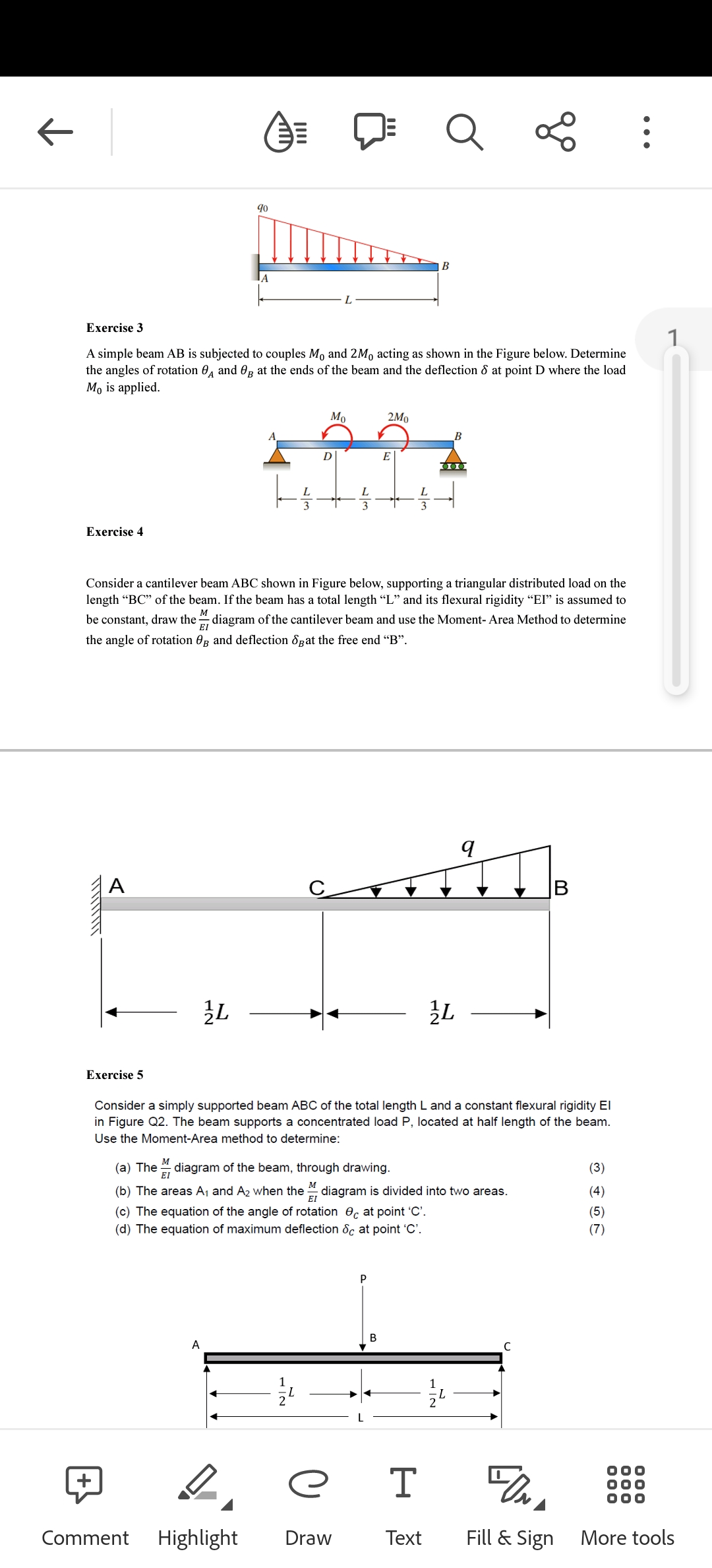
Exercise 4
XXXXXXXXX
A
Exercise 5
3L
e
Exercise 3
A simple beam AB is subjected to couples Mo and 2Mo acting as shown in the Figure below. Determine
the angles of rotation and Og at the ends of the beam and the deflection 8 at point D where the load
Mo is applied.
40
A
A
Comment Highlight
A
D
L
Mo
Consider a cantilever beam ABC shown in Figure below, supporting a triangular distributed load on the
length "BC" of the beam. If the beam has a total length "L" and its flexural rigidity "EI" is assumed to
be constant, draw the diagram of the cantilever beam and use the Moment- Area Method to determine
the angle of rotation Og and deflection at the free end "B".
M
ΕΙ
e
Draw
2Mo
E
P
B
Consider a simply supported beam ABC of the total length L and a constant flexural rigidity El
in Figure Q2. The beam supports a concentrated load P, located at half length of the beam.
Use the Moment-Area method to determine:
(a) The diagram of the beam, through drawing.
M
(b) The areas A₁ and A₂ when the diagram is divided into two areas.
ΕΙ
(c) The equation of the angle of rotation c at point 'C'.
(d) The equation of maximum deflection &c at point 'C'.
Q
B
T
Text
…III
2
L
go
q
L
FON
Fill & Sign
(3)
(4)
(5)
(7)
1
More tools
Expert Solution
This question has been solved!
Explore an expertly crafted, step-by-step solution for a thorough understanding of key concepts.

Step by step
Solved in 7 steps with 3 images

Knowledge Booster


Learn more about
Need a deep-dive on the concept behind this application? Look no further. Learn more about this topic, mechanical-engineering and related others by exploring similar questions and additional content below.Recommended textbooks for you
Mechanics of Materials (MindTap Course List)
Mechanical Engineering
ISBN:
9781337093347
Author:
Barry J. Goodno, James M. Gere
Publisher:
Cengage Learning
Mechanics of Materials (MindTap Course List)
Mechanical Engineering
ISBN:
9781337093347
Author:
Barry J. Goodno, James M. Gere
Publisher:
Cengage Learning