Figure P2.40 2 3 Position 1 Position 2 (a) 2 4 Position 1 Position 2 (b) b Vg (c) Figure P2.40 Full Alternative Text +,


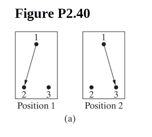
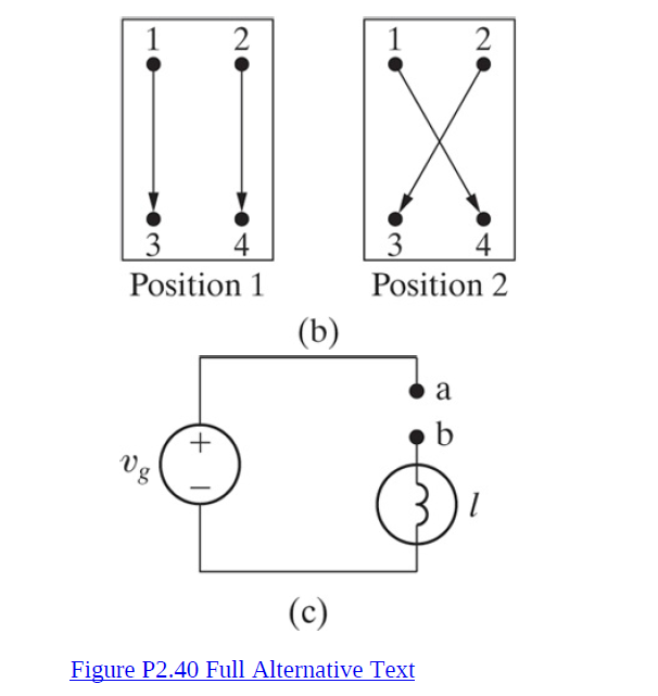
It is often desirable in designing an electric wiring system to be able to control a single appliance from two or more locations, for example, to control a lighting fixture from both the top and bottom of a stairwell. In home wiring systems, this type of control is implemented with three-way and four-way switches. A three-way switch is a three-terminal, two-position switch, and a four-way switch is a fourterminal,two-position switch. The switches are shown schematically in P2.40(a), which illustrates a three-way switch, and 2.40(b), which illustrates a four-way switch.
If the lamp (appliance) is to be controlled from more than two
locations, four-way switches are used in conjunction with two
three-way switches. One four-way switch is required for each
location in excess of two. Show how one four-way switch plus two
three-way switches can be connected between a and b in P2.40(c) to control the lamp from three locations. (Hint: The fourway
switch is placed between the three-way switches.)

Step by step
Solved in 2 steps with 1 images


