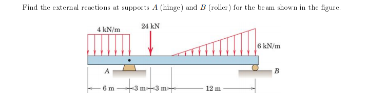
Find the external reactions at supports A (hinge) and B (roller) for the beam shown in the figure. 24 kN 4 kN/m 6 kN/m 6 m 3 m-3 m 12 m


Q: Q- 3. For the given structure below; considering W = 120N &L= 120 cm; a. Draw the Free Body Diagram…
A:
Q: A beam AB is attached to a rocker at A and a pin at B. it is subjected to three forces as shown in…
A:
Q: Anchor of the beam given in the figure is built-in support, B point is movable support and G joint.…
A: Let the reactions at fixed support 'A' be: RAH , RAV , MA. Let the reactions at pin joint 'G' be:…
Q: Cantilever beam is loaded as shown in the figure above. a. Determine the Moment at point O b.…
A:
Q: Calculate the internal reactions for the member along section M-M shown in the Figure. 6 lb/ft 9 ft…
A: Since the end A is knife edge supported thus there will be two support reactions i.e. one in…
Q: A beam (AB) is attached to a roller at A and a pin at B. It is subjected to three concentrated…
A:
Q: 3. A beam is loaded as shown in the figure. Use Three-Moment Equation Method. 60 kN/m C hinge 5 m 3…
A: Given dataUnifomly distributed load UDl = 60kN/mTo determine1]The reaction at the support C2]Compute…
Q: span 5 m is loaded as shown in Figure, Using the principle of virtual work, find the reactions at A…
A:
Q: The constructed shear force diagram (SFD) for the simply supported beam with a Triangle distributed…
A:
Q: H.W. 3 / Find the reactions of the simply supported beam shown in Figure below 200 lb 400 lb-ft A |B…
A: Given RAy=200 lb
Q: Sample Problem: Determine the reactions for the beam loaded as shown in the figure below. 12 KN 15…
A:
Q: The cantilever beam in the figure has a fixed support at A and is under the actions of a uniformly…
A:
Q: Determine the vertical reaction, in KN, at support A for the beam shown in the figure. 2 KN/m- 3…
A:
Q: The overhanging beam is supported by a pin at A and the two-force strut BC as shown in Figure Q4.1.…
A:
Q: For the beam shown below , Find the support reactions at A and B *
A:
Q: 6. The upper beam in Figure 1-64 is supported at D and a roller at C which separates the upper and…
A: Find the reactions at point A,B,C and D.
Q: A simply supported beam AB supports a trapezoid ally distributed load (see figure). The intensity of…
A: →First calculating Reactions:∑MB=0⇒RA(4)−25(4)42−25×42×2×43=0⇒RA=83.33kN+↑…
Q: AB is a cantilever beam and carries two horizontal loads and a vertical load as shown in the figure.…
A:
Q: 5. The two 12-ft beams shown in the figure are to be moved horizontally with respect to each other…
A: For solution refer below images.
Q: Two 10”-15.3 lb channels are welded together as shown in the figure. Find the moment of area of the…
A: mass of each bar is given as=15.3 Lb
Q: Calculate the support reaction at A and B for the beam shown in the figure below. Take F= 570 N.
A: Given: F=570 N To determine: Reaction forces
Q: There is an inclined beam with pin and roller supports at B and A, respectively. The vertical…
A: Convert Uniformly varying load into point load and draw free body diagram of beam.
Q: 18 kN A AZ 2 m 4 m B
A:
Q: Determine the reactions at the supports for the beam shown in Fig. 3.19(a).
A: In this problem we have one point load at C 160 kN and one UDL of 15 kNm over 6 m from A to B and…
Q: Statics
A:
Q: Calculate the vertical external reaction at the hinge support shown in the figure below. 30 kN 45…
A:
Q: 1. Calculate the support reactions, calculate internal forces on the designated section C, and plot…
A: as per our guidelines . i am giving the answer of 1st question. if you want to know the solution of…
Q: Problem 3. Problem. The upper beam in figure is supported by a reaction R3 at D and a roller at C…
A:
Q: In the figure below, the load that the pin at point O can safely carry is 5 kN. In this case, find…
A:
Q: Problem 1. For the frame shown in the figure, determine (a) Reactions at the supports (b) Axial…
A: a) At equilibrium, Taking moment about A, ∑MA=0 -8×5-12×322-25×3-30×7.5-12×15-10×7+12VF=0VF=53.67 N…
Q: :for the figure shown below, calculate the reactions at the point O 30° 15 kN-m 3 kN A B 1.4 kN F1.2…
A:
Q: Specily where th (c) Find the support reactions at A and C (As shown in the figure, A is a pin…
A:
Q: Segments AB and BC of beam ABC arepin connected a small distance tothe right ofjoint B (sec figure).…
A: Strength Of Material
Q: 15 kN 5 kN/m The simply supported beam with a distributed load and couple moment at its center as…
A:
Q: A beam AB is 14 m long weighs 15 N resting on the two supports at the end. If the beam carries loads…
A:
Q: Figure 3 represents a cantilever beam A, B, C, D, E clamped at point E and carrying various types of…
A: Cantilever beam A cantilever beam is a member with one end projecting beyond the point of support,…
Q: The beam AB in the figure supports a load which varies from an intensity of 50 KN per linear meter…
A: This numerical is related to the strength of material portion. Concept is used Convert actual…
Q: Pair of beams (AB) and (CDE) are connected by cable BC and subjected to the concentrated and…
A:
Q: Calculate the support reaction(s) at A and B for the beam loaded as shown. Show the direction of the…
A:
Q: Q1: For structure shown in Figure, Find the reactions of the hinge force at A, B, and C. 2 m 200 N/m…
A:
Q: A beam 12m long is resting on supports at each end. If the beam carries loads at the positions shown…
A:
Q: 2) For the Simply Supported Beam Carrying Four point loads, as shown in the Figure, (a)…
A:
Q: B 1.5 0.5 0.5 (14 kN) (s0 kN)
A:
Q: Determine the reaction of the supports in the figure below.
A: As per the given figure point, C is the internal hinge. So divide the beam in two parts from the…
Q: H.W. 4 / Find the reactions of the simply supported beam shown in Figure below 50 kN 30 KN/m Int.…
A: As per our guideline we suppose to answer only one question. Kindly repost other questions as a…
Q: The beam AB in the figure supports a load which varies from an intensity of 50 KN per linear meter…
A:
Q: A beam (AB) is attached to a roller at A and a pin at B. It is subjected to three concentrated…
A:
Q: H.W. 4 / Find the reactions of the simply supported beam shown in Figure below 50 kN 30 kN/m Int.…
A:
Q: . A homogeneous rod of constant cross section is attached to unyielding supports. It carries an…
A:
Q: Find the support forces at Points A and B by showing the free body diagram in the simple beam given…
A: Convert the uniformly distributed load to a point load, P1=12 kN/m×4 m=48 kN Convert the uniformly…


Trending now
This is a popular solution!

Step by step
Solved in 2 steps with 1 images


- During construction of a highway bridge, the main girders are cantilevered outward from one pier toward the next (see figure). Each girder has a cantilever length of 48 m and an I-shaped cross section with dimensions shown in the figure. The load on each girder (during construction) is assumed to be 9,5 kN/m, which includes the weight of the girder. Determine the maximum bending stress in a girder due to this load.A horizontal beam AB is pin-supported at end A and carries a clockwise moment M at joint B, as shown in the figure. The beam is also supported at C by a pinned-end column of length L: the column is restrained laterally at 0.6Z, from the base at D. Assume the column can only buckle in the plane of the frame. The column is a solid steel bar (E = 200 GPa) of square cross section having length L = 2.4 m and side dimensions h = 70 mm. Let dimensions d = LI2. Based upon the critical load of the column, determine the allowable moment M if the factor of safety with respect to buckling is n = 2.0.Segments AB and BCD of beam ABCD are pin connected at x = 10 ft. The beam is supported by a pin support at A and roller supports at C and D; the roller at D is rotated by 30* from the x axis (see figure). A trapezoidal distributed load on BC varies in intensity from 5 lb/ft at B to 2.5 lb/ft at C. A concentrated moment is applied at joint A, and a 40-lb inclined load is applied at the mid-span or CD. (a) Find reactions at supports A, C, and D. (b) Find the resultant force in the pin connection at B. (c) Repeat parts (a) and (b) if a rotational spring(kr= 50 ft-lb/radian ) is added at A and the roller at C is removed.
- Uniform load q = 10 lb/ft acts over part of the span of fixed-end beam AB (see figure). Upward load P = 250 lb is applied 9 ft to the right of joint A. Find the reactions at A and B.A temporary wood flume serving as a channel for irrigation water is shown in the figure. The vertical boards forming the sides of the flume are sunk in the ground, which provides a fixed support. The top of the flume is held by tic rods that are tightened so that there is no deflection of the boards at that point. Thus, the vertical boards may be modeled as a beam AB, supported and loaded as shown in the last part of the figure. Assuming that the thickness t of the boards is 1,5 in., the depth d of the water is 40 in., and the height h to the tie rods is 50 in., what is the maximum bending stress in the boards? Hint: The numerically largest bending moment occurs at the fixed support.Two flat beams AB and CD, lying in horizontal planes, cross at right angles and jointly support a vertical load P at their midpoints (see figure). Before the load P is applied, the beams just touch each other. Both beams are made of the same material and have the same widths. Also, the ends of both beams are simply supported. The lengths of beams AB and CD are LABand LCD, respectively. What should be the ratio tABltCDof the thicknesses of the beams if all four reactions arc to be the same?
- An overhanging beam ABC has a guided support at A, a rectangular cross section, and supports an upward uniform load q = PtL over AB and a downward concentrated load P at the free end C {see figure). The span length from A to B is L, and the length of the overhang is L12. The cross section has a width of A and a height A. Point D is located midway between the supports at a distance d from the top face of the beam. Knowing that the maximum tensile stress (principal stress) at point Z> is tr, = 38 MPa, determine the magnitude of the load P. Data for the beam are L = 1.75 m, b = 50 mm, // = 220 mm, and d = 55 mm.The cantilever beam ACE shown in the figure has FlexuraI rigidity EI = 2,1 x 10⁶kip-in". Calculate the downward deflections Scand 8Sat points C and B, respectively, due to the simultaneous action of the moment of 35 kip-in. applied at point C and the concentrated load of 2,5 kips applied at the free end B.A framework A BCD is acted on by force P at 2L/3 from 8(see figure). Assume that 7f/is constant. Find expressions for reactions at supports B and C. Find expressions for angles of rotation at A, B* C, and D. Find expressions for horizontal deflections èAand ôD. If length LAB= L i 2, find length LCDin terms of L for the absolute value of the ratio
- A propped cantilever beam, fixed at the left-hand end A and simply supported at the right-hand end B, is subjected to a temperature differentia] with temperature T1on its upper surface and T2on its lower surface (see figure).A propped cantilever beam is loaded by a triangular distributed load from A to C (sec figure). The load has a peak intensity q0= 10 lb/ft. The length of the beam is 12 ft. Find support reactions at A and B.The compound beam ABC shown in the figure has a sliding support at A and a fixed support at C. The beam consists of two members joined by a pin connection (i.e., moment release) at B. Find the deflection