
Mechanics of Materials (MindTap Course List)
9th Edition
ISBN: 9781337093347
Author: Barry J. Goodno, James M. Gere
Publisher: Cengage Learning
expand_more
expand_more
format_list_bulleted
Videos
Textbook Question
Chapter 8, Problem 8.4.10P
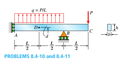
An overhanging beam ABC has a guided support at A, a rectangular cross section, and supports an upward uniform load q = PtL over AB and a downward concentrated load P at the free end C {see figure). The span length from A to B is L, and the length of the overhang is L12. The cross section has a width of A and a height A. Point D is located midway between the supports at a distance d from the top face of the beam.
Knowing that the maximum tensile stress (principal stress) at point Z> is tr, = 38 MPa, determine the magnitude of the load P. Data for the beam are L = 1.75 m, b = 50 mm, // = 220 mm, and d = 55 mm.
Expert Solution & Answer

Trending nowThis is a popular solution!

Chapter 8 Solutions
Mechanics of Materials (MindTap Course List)
Ch. 8 - A spherical balloon is filled with a gas. The...Ch. 8 - A spherical balloon with an outer diameter of 500...Ch. 8 - A large spherical tank (see figure) contains gas...Ch. 8 - Solve the preceding problem if the internal...Ch. 8 - A hemispherical window (or viewport) in a...Ch. 8 - A rubber ball (sec figure) is inflated to a...Ch. 8 - (a) Solve part (a) of the preceding problem if the...Ch. 8 - A spherical steel pressure vessel (diameter 500...Ch. 8 - A spherical tank of diameter 48 in. and wall...Ch. 8 - Solve the preceding problem for the following...
Ch. 8 - A spherical stainless-steel tank having a diameter...Ch. 8 - Solve the preceding problem if the diameter is 480...Ch. 8 - : A hollow, pressurized sphere having a radius r =...Ch. 8 - A fire extinguisher tank is designed for an...Ch. 8 - Prob. 8.3.2PCh. 8 - A scuba t a n k (see fig ure) i s bci ng d e...Ch. 8 - A tall standpipc with an open top (see figure) has...Ch. 8 - An inflatable structure used by a traveling circus...Ch. 8 - A thin-walled cylindrical pressure vessel of a...Ch. 8 - A strain gage is installed in the longitudinal...Ch. 8 - A circular cylindrical steel tank (see figure)...Ch. 8 - A cylinder filled with oil is under pressure from...Ch. 8 - Solve the preceding problem if F =90 mm, F = 42...Ch. 8 - A standpipe in a water-supply system (see figure)...Ch. 8 - A cylindrical tank with hemispherical heads is...Ch. 8 - : A cylindrical tank with diameter d = 18 in, is...Ch. 8 - A pressurized steel tank is constructed with a...Ch. 8 - Solve the preceding problem for a welded Tank with...Ch. 8 - A wood beam with a cross section 4 x 6 in. is...Ch. 8 - Prob. 8.4.2PCh. 8 - A simply supported beam is subjected to two point...Ch. 8 - A cantilever beam with a width h = 100 mm and...Ch. 8 - A beam with a width h = 6 in. and depth h = 8 in....Ch. 8 - Beam ABC with an overhang BC is subjected to a...Ch. 8 - A cantilever beam(Z, = 6 ft) with a rectangular...Ch. 8 - Solve the preceding problem for the following...Ch. 8 - A simple beam with a rectangular cross section...Ch. 8 - An overhanging beam ABC has a guided support at A,...Ch. 8 - Solve the preceding problem if the stress and...Ch. 8 - A cantilever wood beam with a width b = 100 mm and...Ch. 8 - . A cantilever beam (width b = 3 in. and depth h =...Ch. 8 - A beam with a wide-flange cross section (see...Ch. 8 - A beam with a wide-flange cross section (see...Ch. 8 - A W 200 x 41.7 wide-flange beam (see Table F-l(b),...Ch. 8 - A W 12 x 35 steel beam is fixed at A. The beam has...Ch. 8 - A W 360 x 79 steel beam is fixed at A. The beam...Ch. 8 - A W 12 X 14 wide-flange beam (see Table F-l(a),...Ch. 8 - A cantilever beam with a T-section is loaded by an...Ch. 8 - Beam A BCD has a sliding support at A, roller...Ch. 8 - , Solve the preceding problem using the numerical...Ch. 8 - A W 12 x 35 steel cantilever beam is subjected to...Ch. 8 - A W 310 x 52 steel beam is subjected to a point...Ch. 8 - A solid circular bar is fixed at point A. The bar...Ch. 8 - A cantilever beam with a width h = 100 mm and...Ch. 8 - Solve the preceding problem using the following...Ch. 8 - A cylindrical tank subjected to internal...Ch. 8 - A cylindrical pressure vessel having a radius r =...Ch. 8 - A pressurized cylindrical tank with flat ends is...Ch. 8 - A cylindrical pressure vessel with flat ends is...Ch. 8 - The tensional pendulum shown in the figure...Ch. 8 - The hollow drill pipe for an oil well (sec figure)...Ch. 8 - Solve the preceding problem if the diameter is 480...Ch. 8 - . A segment of a generator shaft with a hollow...Ch. 8 - A post having a hollow, circular cross section...Ch. 8 - A sign is supported by a pole of hollow circular...Ch. 8 - A sign is supported by a pipe (see figure) having...Ch. 8 - A traffic light and signal pole is subjected to...Ch. 8 - Repeat the preceding problem but now find the...Ch. 8 - A bracket ABCD having a hollow circular cross...Ch. 8 - A gondola on a ski lift is supported by two bent...Ch. 8 - Beam A BCD has a sliding support at A, roller...Ch. 8 - A double-decker bicycle rack made up of square...Ch. 8 - A semicircular bar AB lying in a horizontal plane...Ch. 8 - Repeat Problem 8.5-22 but replace the square tube...Ch. 8 - An L-shaped bracket lying in a horizontal plane...Ch. 8 - A horizontal bracket ABC consists of two...Ch. 8 - , An arm A BC lying in a horizontal plane and...Ch. 8 - A crank arm consists of a solid segment of length...Ch. 8 - A moveable steel stand supports an automobile...Ch. 8 - A mountain bike rider going uphill applies a force...Ch. 8 - Determine the maximum tensile, compressive, and...Ch. 8 - Prob. 8.5.32PCh. 8 - A plumber's valve wrench is used to replace valves...Ch. 8 - A compound beam ABCD has a cable with force P...Ch. 8 - A steel hanger bracket ABCD has a solid, circular...
Knowledge Booster


Learn more about
Need a deep-dive on the concept behind this application? Look no further. Learn more about this topic, mechanical-engineering and related others by exploring similar questions and additional content below.Similar questions
- -14 A simply supported composite beam with a 3.6 m span supports a triangularly distributed load of peak intensity q0at mid-span (see figure part a). The beam is constructed of two wood joists, each 50 mm x 280 mm, fastened to two steel plates, one of dimensions 6 mm × 80 mm and the lower plate of dimensions 6 mm x 120mm (see figure part b). The modulus of elasticity for the wood is 11 GPa and for the steel is 210 GPa. If the allowable stresses are 7 MPa for the wood and 120 MPa for the steel, find the allowable peak load intensity q0maxwhen the beam is bent about the z axis. Neglect the weight of the beam.arrow_forwardA simply supported wooden I-beam with a 12-ft span supports a distributed load of intensity q = 90 lb/ft over its length (see figure part a). The beam is constructed with a web of Douglas-fir plywood and flanges of pine glued to the web, as shown in the figure part b. The plywood is 3/8 in. thick: the flanges are 2 in, × 2 in, (actual size). The modulus of elasticity for the plywood is 1,600,000 psi and for the pine is 1,200,000 psL Calculate the maximum bending stresses in the pine flanges and in the plywood web. What is q, if allowable stresses are 1600 psi in the flanges and 1200 psi in the web?arrow_forwardA W 12 x 50 steel wide-flange beam and a segment of a 4-inch thick concrete slab (see figure) jointly resist a positive bending moment of 95 kip-ft. The beam and slab are joined by shear connectors that are welded to the steel beam. (These connectors resist the horizontal shear at the contact surface.) The moduli of elasticity of the steel and the concrete are in the ratio 12 to 1. Determine the maximum stresses r1 and xtin the steel and concrete, respectively. Note: See Table F-l(a) of Appendix F for the dimensions and properties of the steel beam.arrow_forward
- Two flat beams AB and CD, lying in horizontal planes, cross at right angles and jointly support a vertical load P at their midpoints (see figure). Before the load P is applied, the beams just touch each other. Both beams are made of the same material and have the same widths. Also, the ends of both beams are simply supported. The lengths of beams AB and CD are LABand LCD, respectively. What should be the ratio tABltCDof the thicknesses of the beams if all four reactions arc to be the same?arrow_forwardA beam with a guided support and 10-ft span supports a distributed load of intensity q = 660 lb/ft over its first half (see figure part a) and a moment Mq = 300 ft-lb at joint B. The beam consists of a wood member (nominal dimensions 6 in. x 12 in. and actual dimensions 5.5 in. x 11.5 in. in cross section, as shown in the figure part b) that is reinforced by 0.25-in.-thick steel plates on top and bottom. The moduli of elasticity for the steel and wood are £s = 30 X 106 psi and £"w = 1.5 X 10⁶ psi, respectively. Calculate the maximum bending stresses trs in the steel plates and rw in the wood member due to the applied loads. If the allowable bending stress in the steel plates is = 14,000 psi and that in the wood is (T.dV!= 900 psi, find qmiiX. (Assume that the moment at .fi, A/0, remains at 300 ft-lb.) If q = 660 lb/ft and allowable stress values in part (b) apply, what is Müm^ at B?arrow_forward(a) A simple beam AB with length L and height h supports a uniform load of intensity q (see the figure part a). Obtain a formula for the curvature shortening A of this beam. Also, obtain a formula for the maximum bending stress b in the beam due to the load q. Now assume that the ends of the beam are pinned so that curvature shortening is prevented and a horizontal force H develops at the supports (see the figure part b). Obtain a formula for the corresponding axial tensile stress t . Using the formulas obtained in parts (a) and (b), calculate the curvature shortening , the maximum bending stress b, and the tensile stress t for the following steel beam: length L = 3m, height h = 300 mm, modulus of elasticity E = 200 GPa, and moment of inertia I = 36 x 106 mm4. Also, the load on the beam has intensity q = 25 kN/m. Compare the tensile stress tproduced by the axial forces with the maximum bending stress bproduced by the uniform load.arrow_forward
- The cantilever beam AB shown in the figure is an S6 × 12.5 steel I-beam with E = 30 × 106 psi. The simple beam DE is a wood beam 4 in. x 12 in. (nominal dimensions) in cross section with E = 1.5 x 10⁶ psi. A steel rod AC of diameter 0.25 in., length 10 ft, and E = 30 x 106 psi serves as a hanger joining the two beams. The hanger fits snugly between the beams before the uniform load is applied to beam DE. Determine the tensile force Fin the hanger and the maximum bending moments MABand MDEin the two beams due to the uniform load, which has an intensity q = 400 lb/ft. Hint: To aid in obtaining the maximum bending moment in beam DE, draw the shear-force and bending-moment diagrams.arrow_forwardBeam ABCD represents a reinforced-concrete foundation beam that supports a uniform load of intensity q1= 3500 lb/ft (see figure). Assume that the soil pressure on the underside of the beam is uniformly distributed with intensity q2 Find the shear force VBand bending moment MBat point B. Find the shear force Vmand bending moment M at the midpoint of the beam.arrow_forwardBeam ABC is fixed at support A and rests (at point B) upon the midpoint of beam DE (see part a of the figure). Thus, beam, ABC may be represented as a propped cantilever beam with an overhang BC and a linearly elastic support of stiffness k at point B (see part b of the figure). The distance from A to B is L = 10 ft, the distance from B to C is L/2 = 5 ft, and the length of beam DE is L = 10 ft. Both beams have the same flexural rigidity EI. A concentrated load P = 1700 lb acts at t lie free end of beam ABC. Determine the reactions RA, RB+ and MAfor beam ABC. Also, draw the shear-force and bending-moment diagrams for beam ABC, labeling all critical ordinates.arrow_forward
- A beam of square cross section (a = length of each side) is bent in the plane of a diagonal (see figure). By removing a small amount of material at the top and bottom corners, as shown by the shaded triangles in the figure, you can increase the section modulus and obtain a stronger beam, even though the area of the cross section is reduced. Determine the ratio ß defining the areas that should be removed in order to obtain the strongest cross section in bending. By what percent is the section modulus increased when the areas arc removed?arrow_forwardA cantilever beam AB having rectangular cross sections with varying width bxand varying height hxis subjected to a uniform load of intensity q (sec figure). If the width varies linearly with x according to the equation hx= bBxiL^ how should the height hxvary as a function of v in order to have a fully stressed beam? (Express hxin terms of the height hBat the fixed end of the beam.)arrow_forwardA cantilever beam AB with rectangular cross sections of a constant width b and varying height /iT is subjected to a uniform load of intensity q (see figure). How should the height hxvary as a function of .y (measured from the free end of the beam) in order to have a fully stressed beam? (Express hxin terms of the height hBat the fixed end of the beam.)arrow_forward
arrow_back_ios
SEE MORE QUESTIONS
arrow_forward_ios
Recommended textbooks for you
 Mechanics of Materials (MindTap Course List)Mechanical EngineeringISBN:9781337093347Author:Barry J. Goodno, James M. GerePublisher:Cengage Learning
Mechanics of Materials (MindTap Course List)
Mechanical Engineering
ISBN:9781337093347
Author:Barry J. Goodno, James M. Gere
Publisher:Cengage Learning
Mechanics of Materials Lecture: Beam Design; Author: UWMC Engineering;https://www.youtube.com/watch?v=-wVs5pvQPm4;License: Standard Youtube License