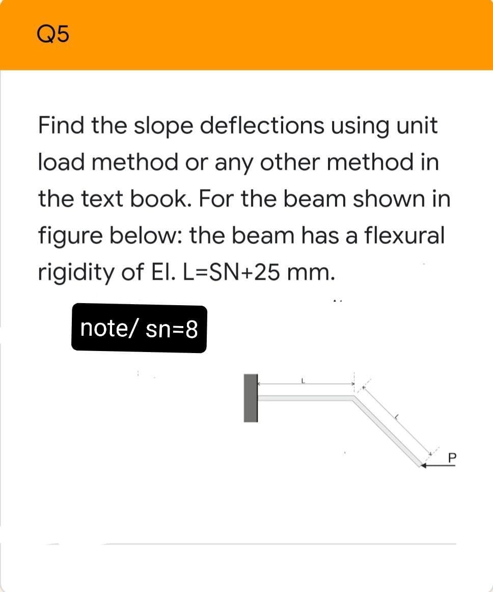
Find the slope deflections using unit load method or any other method in the text book. For the beam shown in figure below: the beam has a flexural rigidity of El. L=SN+25 mm. note/ sn=8
Find the slope deflections using unit load method or any other method in the text book. For the beam shown in figure below: the beam has a flexural rigidity of El. L=SN+25 mm. note/ sn=8

Mechanics of Materials (MindTap Course List)
9th Edition
ISBN:9781337093347
Author:Barry J. Goodno, James M. Gere
Publisher:Barry J. Goodno, James M. Gere
Chapter9: Deflections Of Beams
Section: Chapter Questions
Problem 9.3.16P: A simple beam with an overhang is subjected to d point load P = 6kN. If the maximum allowable...

Related questions
Question
Transcribed Image Text:Q5
Find the slope deflections using unit
load method or any other method in
the text book. For the beam shown in
figure below: the beam has a flexural
rigidity of El. L=SN+25 mm.
note/ sn=8
Expert Solution
This question has been solved!
Explore an expertly crafted, step-by-step solution for a thorough understanding of key concepts.

Step by step
Solved in 2 steps with 2 images

Recommended textbooks for you
Mechanics of Materials (MindTap Course List)
Mechanical Engineering
ISBN:
9781337093347
Author:
Barry J. Goodno, James M. Gere
Publisher:
Cengage Learning
Mechanics of Materials (MindTap Course List)
Mechanical Engineering
ISBN:
9781337093347
Author:
Barry J. Goodno, James M. Gere
Publisher:
Cengage Learning