Find the state table for the circuit


Q: Create a Boolean expression for the logic circuit shown in the diagram below?
A: Given logic diagram:
Q: 12. Draw the truth table for the following circuit diagram. A B
A: Answer:- 12 Given…
Q: For the state diagram shown below write the state table and design logic circuit
A: Solution
Q: A combinational logic circuit has one output (F) and four inputs (a, b, c, and d). The circuit is…
A: Lets see the solution in the next steps
Q: Task 1: Circuit analysis Find the Boolean expression that represents the outputs x and y shown in…
A: LOGIC GATES
Q: Derive the state table and the state diagram of the sequential circuit shown below. Explain the…
A:
Q: Construct the state table and state diagram for the following sequential circuit.
A: The state table and state diagram is an given in below diagram :
Q: O Design a clocked sequential circuit in the following state diagram using D flip flops, then draw…
A: It is defined as Delay Flip Flop or D Flip Flop is the simple gated S-R latch with a NAND inverter…
Q: Exe For the state diagram shown below write the state table and design logic circuit 0/0 %0
A: Given state diagram contains 3 states that are A, B and C. The final state is C and the state table…
Q: PLEASE MAKE A COMPLETE DESCRIBING AND EXPLANATION 1. Describe a sequential
A: A sequential circuit is a logical circuit, where the output depends on the present value of the…
Q: Question 06) Write down the state equations describing the following sequential circuit. Also derive…
A: Answer: I have given answer in the brief explanation
Q: Q1: For the state diagram shown below write the state table and design logic circuit
A: Here let's assign a binary value to each state Start=000 First=001 Second=010 Delay=011 Success=100
Q: Compare the difference between Synchronous and Asynchronous sequential logic circuits. Explain any…
A: Combinational circuits are the Part of the Sequential Circuits to which storage elements are…
Q: Figure shows the diagram for an automobile alarm circuit used to indicate the status of the door,…
A:
Q: The given State Diagram represents a circuit that has two Flip-Flops (A and B), one input (X) and…
A: Given: The above diagram represents a circuit that has two Flip-Flops (A and B), one input (X) and…
Q: For the clocked sequential circuit shown in the figure below, determine the a) state table…
A:
Q: Q2:For the state diagram shown below write the state table and design logic circuit
A: Let us use D flip flop. Let the input be x and output be y. Let states be represented as ABC
Q: Provide state table for following state diagram, and design the mealy machine circuit diagram.
A: In which case in mealy machine state diagram to the state table.
Q: Create a Boolean expressions for the logic circuit shown in the diagram below
A: The diagram of the given logic circuit is The logic circuit has three inputs X, Y, and Z. the…
Q: 1. Analyze the following sequential circuit Derive the (a) state equations (b) state table and (c)…
A: GIVEN:
Q: I. Write down the state equations. II. Write down the output equations. III. Write down the state…
A: 1. Here first we need to find input equation to all the flip-flop from the diagram DA => B.C DB…
Q: A' A B' B Clk Clk T T Clock
A: The given circuit is Mod 3 counter using T flip flop. Which repeatedly count 0,1,2,0,1,2,... State…
Q: Draw the circuit diagram for the given expressions. Show the diagrams on your solution sheet. 1. F =…
A: Here, we are given two expressions and we have to draw the logic circuits. Logic circuit diagram can…
Q: For the state diagram shown below write the state table and design logic circuit EX
A: Given state diagram contains 4 states A, B, C and D where D is the final state. The state table for…
Q: Q2. a) Derive the excitation equations and gutput equation for the following circuit (Figure 1).…
A:
Q: a) Draw the state table of the synchronous sequential circuit, b) Derive the next state equations…
A: Answer in Step 2.
Q: 1 Create a circuit from the given state diagram * llo oll (101 (oll 100
A: Create a circuit from the given state diagram .
Q: Draw the logic diagram of the digital circuit specified by the following Verilog description:
A:
Q: Analyze the following sequential logic circuit. (To show input models, state table and state…
A: Input models Q1 Q0 INPUT X FLIP FLOP INPUT J1 K1 J0 K0 0…
Q: Design a circuit that will function as prescribed by the state diagram shown in Figure 13.38. Use…
A: Question :-
Q: 1. Define the following terms: a) combinational circuit: 5) sequential circuit: E) excitation table:…
A: In digital logic, there are some important key terms that must be cleared before deep dive. E.g…
Q: 2. The state diagram for a circuit made from a single D flip-flop is shown below. The left most loop…
A: Input Current State Next State Output 0 0 0 0 1 0 1 1 1 1 1 1 0 1 0 0
Q: Create the logic circuit diagram for NOT [(x AND y) OR z]. Create the image in logic.ly or draw on…
A: AND operator: The logic gate AND is represented as below OR operator: The logic gate OR is…
Q: The output of a combinational logic circuit is F=A'D'+(A+B) (B'+C'). To remove the static one hazard…
A: If there is an accident in the digital circuit, it can cause temporary fluctuations in the circuit…
Q: FIGURE 11.55 is a state transition diagram for a sequential circuit with three flip-flops and one…
A: To design a sequential circuit with three flip-flops and one input that counts up in binary when the…
Q: Universal Gates Exercise: Redraw the below logic diagram. The new circuit have to consist of AND and…
A: Given logic diagram contains six inputs that are A, B, C, D, E and F. In the given diagram it…
Q: Derive the state table and the state diagram of the sequential circuit shown below and explain the…
A: Here Providing best answers for you.
Q: CP K K a
A:
Q: low the steps below: a. Draw a state diagram. b. Write a state transition table. c. Write state…
A:
Q: Derive the state diagram for the circuit below.
A: let's solve step by step:
Q: Derive the state table and the state diagram of the sequential circuit shown in Fig. P5.8 . Explain…
A: Draw the circuit for a flip-flop. If the input is high, then the flip-flop changes its state…
Q: Q4 A sequential circuit has two (flip flops), one input X, and one output Z. The logic diagram of…
A: 4. The given circuit has 2 flip flops and so there will be 2 output states along with the output…
Q: Obtain the state diagram for the circuit shown below.
A: Answer has been explained below:-
Q: Derive the state table and the state diagram of the sequential circuit shown below . Explain the…
A: Answer The given sequential circuit is The truth table of T-Flip Flop is: Find the equations for…
Q: Q/a sequential circuit has one input and one output.the state diagram as shown. complete the state…
A: state diagram t flip flop
Q: Below is a logic diagram of a sequential circuit. b)Explain whether the circuit is a Mealy or Moore…
A: b)Explain whether the circuit is a Mealy or Moore circuit: The circuit is Mealy. Mealy machine:…
Q: ii) For the circuit shown in figure (Q5-ii), deduce the state diagram for the circuit. 10₂ De D₁ D₂…
A: Given circuit is a sequential circuit which contains three D flip flops. For each flipflop, clock…
Q: Construct the state table and state diagram for the sequential circuit shown below. Explain how the…
A:
Q: Example 3: Design a logic circuit whose output is HIGH only when a majority of the inputs A, B and C…
A: Since you have asked multiple questions, we will solve the first question for you. If you want any…
Q: The output of a combinational logic circuit is F=A'D'+(A+B) (B'+C'). To remove the static one hazard…
A: The question is to choose the correct option from the given four options.
Please show solution to answer
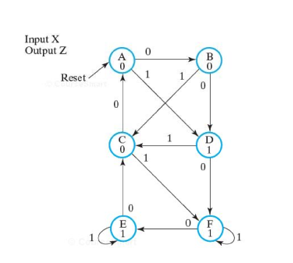
The state diagram for a sequential circuit appears in the following figure.
Find the state table for the circuit


Trending now
This is a popular solution!

Step by step
Solved in 2 steps


- in spike prime using python help me fix this spin algoirthm it is supposed to spin in a circle and get bigger per spin until it is a certain distance away from the wall then the distance sensor tells it to stop. this is the code i have now but it does not work from spike import MotorPair, DistannceSensor, PrimeHub from spike.control import Timer, wait_for_seconds motor_paid = MotorPair('C','D') distance_sensor = DistanceSensor('F') def search1 while true" distance_sensor.wait_for_distance_farther_than(5,'in', short_range = False) motor_pair.move(1000, unit='in', steering= -30, speed = 30) motor_pair.stop() motor_pair.move(10, unit = 'in', steering =-100, speed= 70) motor_pair.stop()USE JOptionPane Create a java program to compute the area and perimeter of a rectangle given thelength and width (in centimeters). Output the area in sq. cm.; sq. m.; sq. in.; and sq. ft.For perimeter in cm.; m.; in.; and ft. Use JOptionPane to get input from the user and to output the result in message box. The image attached is the sample layout of output but using JOptionPane. Don't answer if you don't read the instruction. Thanks.Ttyyyff
- Write a python code that implements dithering as follows:Convert a 24bit image (choose low-resolution image or icon i.e. 400*400) to an 8-bit image.- Show the color lookup table + raster area- the image before and after(use click button)- Provide these 5 (screenshots)sample outputs and tell if each is a palindrome or not.Too bad--I hid a bootSome men interpret eight memos"Go Hang a Salami! I'm a Lasagna Hog"(title of a book on palindromes by Jon Agee, 1991)A man, a plan, a canal—PanamaGateman sees my name, garageman sees name tag LinkedStackADT.javapublic interface LinkedStackADT<T> {boolean isEmptyStack();void push(T val);T peek() throws StackUnderflowException;void pop() throws StackUnderflowException;}=============StackUnderflowException.javapublic class StackUnderflowException extends Exception {public StackUnderflowException(){}public StackUnderflowException(String msg){super(msg);}}=========LinkedStackDS.javapublic class LinkedStackDS<T> implements LinkedStackADT<T>{private class StackNode{T data;StackNode next;StackNode(){}StackNode(T data, StackNode next){this.data = data;this.next = next;}public String toString(){return data.toString();}}private StackNode top;public LinkedStackDS()…What color is the complementary color of yellow? *cyanmagentabluered What would be the resulting output of the Boolean expression, 1 + 0 *no answer10
- Write a program that displays a tic-tac-toe board, asshown in Figure . A cell may be X, O, or empty. What to displayat each cell is randomly decided. The X and O are the image files x.gifand o.gif.2- The bars used to count frequency while constructing a grouped frequency distribution are called: a. Tally marks b. None of the options c. Range d. Barscan you please slove using Matlb app and add copy and paste code for Matlab. thanks
- Fill in the blank question- Only answer without explanation Q. iptables workds based on _______________.Transcribed Image Text Write Program in rust programming language to print sum of even natural numbers in the range 2 to 50 using infinite loop. Attach Output Screenshot.Converting an image to grayscale simplifies the algorithm and reduces computational requirements prior to extracting the image features. Write a Java program to convert a colour image to a grayscale image by manipulating the pixel colour values. The Red : Green : Blue ratio should be set to 28:60:12.