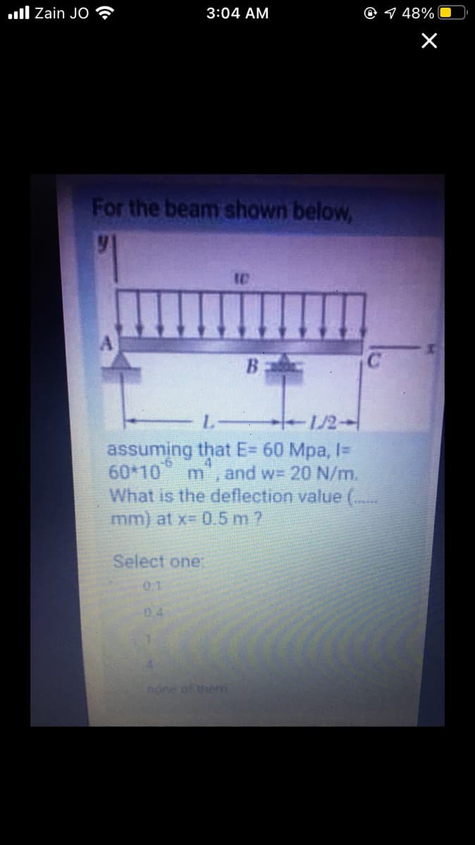
For the beam shown below, B L- t-1/2- assuming that E= 60 Mpa, I= 60*10 m, and w= 20 N/m. What is the deflection value ( mm) at x 0.5 m ? Select one: 0.1 04 none of thenm


Q: Consider the beam arrangement with distributed load of 12 kN/m as shown in Figure 1. ii. Determine…
A: Given Data and Initial Calculation :- for ease of calculatation lets take 20kN instead of 12kN.
Q: A cantilever beam ACB supports two concentrated loads P, and P2, as shown in the following figure.…
A: Draw a diagram for the problem. Here, x is the distance of the cross-section at which the bending…
Q: A I-meter-long, simply supported copper beam (E= 117 GPa) carries uniformly distributed load q. The…
A:
Q: BP4: A simply supported beam of constant El and length L is supporting a distributed load omega w…
A: The given beam is as shown below, To determine deflection at C by Castilagino's method we will…
Q: . Figure shows a simply supported beam of span 5m carrying two point loads. Find a). The deflection…
A:
Q: BP1 A round steel beam with diameter d=1 cm and length L=1 m, supported at L/3 and 2L/3, is loaded…
A: Draw the free-body diagram of the beam.
Q: A cantilever beam has a length L =12 ft anda rectangular cross section (b = 16 in., h = 24 in.).…
A: Calculate the moment of inertia of the beam. I=bh312 Here, I is the moment of inertia of the beam, b…
Q: Question Two For the shown simply supported beam, a deflection of 1.5 mm is developed in the beam at…
A:
Q: a. Show that the best material for a cantilever beam of given length L and given (i.e., fixed)…
A:
Q: Problem 1 [30pts] The cross section of a rectangular beam having width b and height h is shown in…
A: Section modulus on any section is given by Z=Iy Where I=Area Moment of inertia about the axis of…
Q: For the simply supported beam carrying the concentrated load P = 268 N at its midspan, determine the…
A: Use simply support beam concept to solve this problem, Given information Total length of…
Q: 3 typ. 2,8 10 10 13 16,2 15,7
A:
Q: 2. A simple wooden beam, 50 mm wide by 250 mm deep and 7.5 m long has a maximum deflection of 102 mm…
A: Answer: The flexural stress is 27 MPa.
Q: 1. A semi-infinite steel beam of second moment of area I, = 4.0 × 10° mmª is supported on an elastic…
A: Write the given information.
Q: A simple beam AB of length L supports aconcentrated load P at the midpoint (see gure).(a) Evaluate…
A: Given data as per question The load applied =P Calculations ∑Fx=0HA=0∑Fy=0RA+RB=P…
Q: For the beams below, determine the location of the maximum deflection using double integration…
A:
Q: Find the maximum deflection, in inches, for 16ft. long steel beam (E=30x10^6psi) that has 2''x2''…
A: We have to find deflection of beam
Q: (b) A simple beam ABCD with a uniformly loading and a single load at point C is shown in Figure…
A: A beam's deformation is often measured in terms of its deviation from its unloaded position. The…
Q: Consider a fixed beam under uniformly distributed load 'w' as shown in the figure below: w A B…
A: Data given -
Q: Find the slope deflections using any unit load method in the text book. For the beam shown in figure…
A:
Q: Consider the following uniformly loaded simple beam. The beam has a span length L = 2.5 m, the load…
A:
Q: A W310 x 129 I-beam, made of A36 steel, is shown in the figure. This I-beam is 4 m long and has a…
A:
Q: Q/ For the beam shown in the figure below, find deflection and rotation at point B. EI=12000 kN.m2.…
A:
Q: A cantilever 8m long carries a uniformly distributed load of 12kN/m from midspan to free end.…
A:
Q: P B A 21 21 1.50 m 1.50 m 1.50 m 1.50 m
A: given data; ⇒lets take reaction force at A=RA⇒lets take reaction force at…
Q: 7. A 4.5 m long cantilever beam of hollow circular section of diameters 150.0 mm and 100.0 mm…
A:
Q: QUESTION 3 Calculate the vertical deflection at point 'A' for the thin curved beam shown in figure…
A:
Q: P a В A 8 m Question 1 Using double integration method, determine the maximum deflection (EIO) in a…
A:
Q: Q 1. A simple supported beam of span 9m carries two points loads 210 KN & 125 KN at 2m & 6m from…
A: Given:- the span of simple supported beam=9m Uniform distribution load throughout the beam…
Q: For The beam shown in The Figure belw. find deflection at point B FI =12000 KN wm? P= 50 KN M225KN.m…
A:
Q: In the following cantilever beam structure, the equation of elastic curve in the range of 0s x s a…
A: Write the boundary conditions for the cantilever beam.
Q: 5. For the beam shown in the figure, determine the slope at A and B and the value of the maximum…
A: Whenever a beam is subjected to load it tends to bend under loading. This is called deflection of…
Q: A propped cantilever steel beam is constructedfrom a W12 x 35 section. The beam isloaded by its…
A: Given data as per question Length of the beam =11.5 ft E = 30,000 ksi. For W12 x 35 section q =…
Q: 9.5-2 A simply supported beam (E = 12 GPa) car- THes a uniformly distributed load q point load P =…
A:
Q: What is the span length L (in ft) of a uniformly loaded, simple beam of wide-flange cross section…
A: Given : The maximum bending stress = 11400 psi The maximum deflection = 0.1 in The modulus of…
Q: A simply supported beam is loaded with apoint load, as shown in the figure. The beam is a steelwide…
A: Given data as per question P = 10 kips f L =10 ft a = 7 ft b = 3 ft
Q: Find the deflection at the mid-point BC of the loaded beam as shown in the figure by the double…
A:
Q: Calculate the beam deflection at point C. E = 206.8 GPa, In = 1.873 x 10⁻⁶ m4. Use either the double…
A:
Q: mm by 500 mm, methods discussed find the deflection at the free end. Use E 200 GPa Assume P equals 8…
A: Reaction When beam is subjected to load then to keep beam in equilibrium there must be reaction…
Q: 4. A steel bar in Fig. 2 of length L= 2.0 m is compressed by axial load at the midpoint of one side…
A:
Q: bläi 4 For a beam, as shown in the below figure, the deflection at the free end are 8 kN 6kN/m A_c!…
A: A free-body diagram of the above beam is given as, On using force equilibrium in a vertical…
Q: Problem No. 3 Using double integration method to determine the deflection at L and 1.5L for the beam…
A:
Q: For the beam shown, use only singularity functions. V = 50 lbf/in and V2 = 7 in. NOTE: This is a…
A:

Step by step
Solved in 2 steps with 2 images


- A cantilever beam has a length L = 12 ft and a rectangular cross section (b = 16 in., h = 24 in.), A linearly varying distributed load with peak intensity q0acts on the beam, (a) Find peak intensity q0if the deflection at joint B is known to be 0.18 in. Assume that modulus E = 30,000 ksi. (b) Find the location and magnitude of the maximum rotation of the beam.A reinforced concrete T-beam (see figure) is acted on by a positive bending moment of M = 175 kip-ft. Steel reinforcement consists of four bars of 1.41-inch diameter. The modulus of elasticity for the concrete is Ec= 3000 ksi while that of the steel is £s = 29,000 ksi. Let b = 48 im, rf = 4 in., bw=15 in,, and d = 24 in, Find the maximum stresses in steel and concrete, If allowable stresses for concrete and steel are o"ac = 1400 psi and tr^ =18 ksi, respectively, what is the maximum permissible positive bending moment?Beam ACB hangs from two springs, as shown in the figure. The springs have stiffnesses Jt(and k2^ and the beam has flexural rigidity EI. What is the downward displacement of point C, which is at the midpoint of the beam, when the moment MQis applied? Data for the structure are M0 = 7.5 kip-ft, L = 6 ft, EI = 520 kip-ft2, kx= 17 kip/ft, and As = 11 kip/ft. Repeat part (a), but remove Af0 and instead apply uniform load q over the entire beam.
- Beam ABC is loaded by a uniform load q and point load P at joint C. Using the method of superposition, calculate the deflection at joint C. Assume that L = 4 m, a =2ra, q = 15 kN/m, P = 7.5 kN, £ = 200 GPa, and / = 70.8 X 106 mm4.A r o lukI f/frm f «m t ub e of ou t sid e d ia met er ^ and a copper core of diameter dxare bonded to form a composite beam, as shown in the figure, (a) Derive formulas for the allowable bending moment M that can be carried by the beam based upon an allowable stress <7Ti in the titanium and an allowable stress (u in the copper (Assume that the moduli of elasticity for the titanium and copper are Er- and £Cu, respectively.) (b) If d1= 40 mm, d{= 36 mm, ETl= 120 GPa, ECu= 110 GPa, o-Ti = 840 MPa, and ctqj = 700 MPa, what is the maximum bending moment Ml (c) What new value of copper diameter dtwill result in a balanced design? (i.e., a balanced design is that in which titanium and copper reach allow- able stress values at the same time)..2 A ligmio.irc ii supported by two vorlical beams consistins: of thin-walled, tapered circular lubes (see ligure part at. for purposes of this analysis, each beam may be represented as a cantilever AB of length L = 8.0 m subjected to a lateral load P = 2.4 kN at the free end. The tubes have a constant thickness ; = 10.0 mm and average diameters dA = 90 mm and dB = 270 mm at ends A and B, re s pec lively. Because the thickness is small compared to the diameters, the moment of inerlia at any cross section may be obtained from the formula / = jrrf3;/8 (see Case 22, Appendix E); therefore, the section modulus mav be obtained from the formula S = trdhlA. (a) At what dislance A from the free end docs the maximum bending stress occur? What is the magnitude trllul of the maximum bending stress? What is the ratio of the maximum stress to the largest stress (b) Repeat part (a) if concentrated load P is applied upward at A and downward uniform load q {-x) = 2PIL is applied over the entire beam as shown in the figure part b What is the ratio of the maximum stress to the stress at the location of maximum moment?
- A simple beam AB of length L and height h (see figure) is heated in such a manner that the temperature difference 7= T{between the bottom and top of the beam is proportional to the distance from support A: that is, assume the temperature difference varies linearly along the beam: T2- Tt= Tax in which 7"0 is a constant having units of temperature (degrees) per unit distance. Determine the maximum deflection SW9Xof the beam, Repeat for a quadratic temperature variation along the beam, so T2+T1= TaxA simple beam with an overhang is subjected to d point load P = 6kN. If the maximum allowable deflect ion at point C is 0.5 mm, select the lightest W360 section from Table F-l{b) that can be used for the beam. Assume that L = 3 m and ignore the distributed weight of the beam.A cantilever beam of a length L = 2.5 ft has a rectangular cross section {b = 4in,, h = Sin,) and modulus E = 10,000 ksi. The beam is subjected to a linearly varying distributed load with a peak intensity qQ= 900 lb/ft. Use the method of superposition and Cases 1 and 9 in Table H-l to calculate the deflection and rotation at B.
- Solve the preceding problem for a box beam with dimensions h = 0.5 m, h = 0.18 m, and t = 22 mm. The yield stress of the steel is 210 MPa.A simple beam that is 18 ft long supports a uniform load of intensity q. The beam is constructed of two C8 x 11.5 sections (channel sections or C-shapes) on either side of a 4 × 8 (actual dimensions) wood beam (see the cross section shown in the figure part a). The modulus of elasticity of the steel (E; = 30,000 ksi) is 20 times that of the wood (Ew). (a) If the allowable stresses in the steel and wood are 12,000 psi and 900 psi, respectively, what is the allowable load qmax Note: Disregard the weight of the beam, and see Table F-3(a) of Appendix F for the dimensions and properties of the C-shape beam. (b) If the beam is rotated 90° to bend about its v axis (see figure part b) and uniform load q = 250 lb/ft is applied, find the maximum stresses trs and crw in the steel and wood, respectively Include the weight of the beam. (Assume weight densities of 35 lb/ft3 and 490 lb/ft3 for the wood and steel, respectively.)A simply supported beam (E = 1600 ksi) is loaded by a triangular distributed load from A to C(see figure). The load has a peak intensity q0= 10 lb/ ft, and the deflection is known to be 0.01 in, at point C. The length of the beam is 12 ft, and the ratio of the height to the width of the cross section is (h:b) 2:1, Find the height h; and width h of the cross section of the beam.