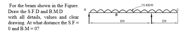
For the beam shown in the Figure. 15 KN/m Draw the S.F.D and B.M.D with all details, values and clear drawing. At what distance the S.F = O and B.M = 0? 6m 2m
Q: Q1: A simply supported beam as shown in figure (1-A) below, having an I-cross section, has an over…
A:
Q: Design a timber glue-lam beam made from douglas fir for the given load in the figure below. 670…
A:
Q: Q1: A simply supported beam as shown in figure (1-A) below, having an I-cross section has an over…
A: Given simply supported Beam with I section as shown below
Q: QUESTION 1 A beam of rectangular section as shown in Figure 1 carries a load of 2 kN at mid-span.…
A: Givensimply supported beam as shown in figure below-F=2kNL=3.6md=2bσblimit=9N/mm2
Q: |1200 Ib | 1200 Ib 3 ft R2
A: Note: As per bartelby guideline first three subpart are solved. please upload other part separately…
Q: Figure shows a 90° cantilever (dark blue line), with dimensions and coordinate system directions…
A: We need to use Castigleanos theorem to determine the deflection....
Q: Three plates are welded together to form the curved beam shown in the figure for M = 8 kip * in.…
A: We locate the centroid of the cross section (1) 4.875 (2)…
Q: Q1: A simply supported beam as shown in figure (1-A) below, having an I-cross sec has an over all…
A:
Q: The simply supported W8X24 A-36 steel beam AB is loaded as shown in the figure. What is the slope of…
A:
Q: required width (bmin) if the allowable bending stress in the material is 16 MPa ? If the beam shown…
A:
Q: If w = 25 kN/m., calculate the value of EIδ at 1 m. of the free end of the loaded beam as indicated…
A:
Q: Required information Consider the beam shown in the given figure. NOTE: This is a multi-part…
A:
Q: Find the slope deflections using unit load method or any other method in the text book. For the beam…
A:
Q: A beam ABCDE is 5 m in length and loaded as shown in Fig.3. Draw the S.F. and B.M. diagrams for the…
A:
Q: As shown in the figure below, determine the internal loadings at points D and. Consider the weight…
A: given: FN = 70lbs SN = 50lb/ft
Q: Q1: A simply supported beam as shown in figure (1-A) below, having an I-cross section, has an over…
A: Given Data: The uniformly distributed load acting on the beam is w1= 30 kN/m over the span of 1.5 m…
Q: The cantilever beam, whose loading condition and cross-section are given in the figure, is ideal…
A:
Q: Find the slope deflections using unit load method or any other method in the text book. For the beam…
A: The deviation is the level at which a structural element is moved under the load (due to its…
Q: 6 kN 30° 30° 1.5 m 4 kN -1.5 m-
A:
Q: Q2// B) For the simply supported T-beam shown in Fig. (3), check the adequacy of the cross-section…
A: Given, A T section. Yield stress Fy = 400 Mpa. Total load acting on the beam , WL + Wd = W =…
Q: Q3: If the figure (2) below shows a bending moment diagram (B.M.D) for the beam CABD, then the load…
A: Bending moment is defined as an internal force resulted from the action of external loads or moments…
Q: Draw SFD & BMD of the beams shown below. Then determine their maximum tensile and compressive…
A:
Q: "Draw the shear and moment diagrams or the beams shown in the figure below
A:
Q: F L h Figure Q1 b) State if the cantilever beam is in plain stress or plain strain and explain…
A: given; lets take width of beam=b lets take reaction force=R
Q: An I-section shown in Fig. is simply supported over a span of 15 m. If the maximum permissible…
A:
Q: (a) Calculate the required section modulus S if Oallow = 18,000 psi, L = 32 ft, P = 2900 lb, and q =…
A:
Q: For the simply supported beam shown in the figure, if (q=30 KN/m) and (L=6m), then, the point of…
A: Consider the free body diagram of the beam as shown below. The distributed load can be assumed to…
Q: Example: Draw Shear & Moment diagram for the following beam
A:
Q: Q-5. Calculate the maximum allowable internal bending moment M that can be applied to the beam. The…
A: The given figure is symmetrical, and thus the centroid will lie at the mid of the section. The…
Q: Q1: A simply supported beam as shown in figure (1-A) below, having an I-cross section, has an over…
A: Given dataUDL on 1.5m span UDL1.5 = 30kN/mPoints loads of each 20kN and 10kNUDL on 1m span UDL1 =…
Q: Q1: A simply supported beam as shown in figure (1-A) below, having an I-cross section, has an over…
A: As per our guideline we are supposed to do 1st question only. kindly post 2nd question separately.…
Q: a) What is the importance of SFD and BMDs for structural engineers? b) For the beam and loading…
A:
Q: The simple beam shown carries a uniform load w, = 10 kN/m. The dimensions a, b, c, and d are 0.6 m,…
A: Draw the free-body diagram of the beam.
Q: A simply supported wood beam having a span length L=12ft is subjected to unsymmetrical point loads.…
A:
Q: required width (bmin) if the allowable bending stress in the material is 16 MPa? If the beam shown…
A:
Q: 1. Find the maximum tensile and compressive flexural stresses for the cantilever beam with loading…
A:
Q: Question 5 a) What is the importance of SFD and BMDs for structural engineers? b) For the beam and…
A:
Q: For beam load shown identify the following items. a. Maximum shear force is b. Maximum moment is C.…
A: given data; ⇒load intensity (w)=0.5K/ft=1.102lb/ft⇒AB=16ft⇒lets take reaction force at A=RA⇒and…
Q: Q1: A simply supported beam as shown in figure (1-A) below, having an I-cross section, has an over…
A:
Q: 2. A cantilever, made of a certain material, of 2 m length and square section 212 mm on its side,…
A: Given:Lc=2 mac=212mmP=13,252NLs=3mbs=150mmds=300mm
Q: the beam under the external loadings shown in the figure. Note: use the graphical method; show all…
A: This question is from solid mechanics.
Q: Draw shear force and bending moment diagrams for the beam and loading in the figure.
A:
Q: A simply supported beam is loaded with apoint load, as shown in the figure. The beam is a steelwide…
A: Given data as per question P = 10 kips f L =10 ft a = 7 ft b = 3 ft
Q: For the beam loaded as shown in figure, the maximum bending moment will appear
A: Consider the element AB, Consider the element BC,
Q: Cantilever beam loaded as shown in fig., draw the shear force diagram and bending moment diagram. 20…
A:
Q: B/ Draw shear and bending moment diagram for beam loading as shown in Fig. below:
A:
Q: The cantilever beam whose details are given in Figure, if E = 200 00O N/mm2. Answer all the…
A:
Q: A cantilever beam of length 6 m (Figure 1) carries point loads of 4 kN and 3 kN at a midspan and…
A:
Step by step
Solved in 3 steps with 3 images
- The deflection curve for a cantilever beam AB (sec figure) is given by v=q0x2120LEI(10L210L2x+5Lx2x3) Describe the load acting on the beam.A weight W = 20 kN falls through a height h = 1,0 mm onto the midpoint or a simple beam of length L = 3 m (see figure). The beam is made of wood with square cross section (dimension don each side) and E = 12 GPa. If the allowable bending stress in the wood is °aLLow =10MPa, what is the minimum required dimensionA simple beam with an overhang is subjected to d point load P = 6kN. If the maximum allowable deflect ion at point C is 0.5 mm, select the lightest W360 section from Table F-l{b) that can be used for the beam. Assume that L = 3 m and ignore the distributed weight of the beam.
- A steel plate (called a cover ploie) having cross-sectional dimensions 6,0 in. × 0.5 in. is welded along the full length of the bottom flange of a W 12 × 50 wide-flange beam (sec figure, which shows the beam cross section). What is the percent increase in the smaller section modulus (as compared to the wide-flange beam alone)?Two wood beams, each of rectangular cross section (3.0 in. x 4.0 in., actual dimensions), are glued together to form a solid beam with dimensions 6.0 in. x 4.0 in. (sec figure). The beam is simply supported with a span of S ft. What is the maximum moment Mmaxthat may be applied at the left support if the allowable shear stress in the glued joint is 200 psi? (Include the effects of the beams own weight, assuming that the wood weighs 35 lb/ft3.) Repeat part (a) if Mmaxis based on allowable bending stress of 2500 psi.A weight W = 4000 lb falls through a height h = 0.5 in, onto the midpoint of a simple beam of length L = 10 ft (see figure). Assuming that the allowable bending stress in the beam is = 18,000 psi and E = 30 x 10* psi, select the lightest wide-flange beam listed in Table F-l(a) in Appendix F that will be satisfactory.
- A fixed-end b earn is subjected to a point load at mid-span. The beam has a rectangular cross section (assume that the h/b ratio is 2) and is made of wood (E = 11GPa). Find height h of the cross section if the maximum displacement of the beam is 2 mm. Calculate the displacement of the beam at the inflection points.-3 The deflection curve for a simple beam AB (see figure) is given by v=q0x360LEI(7L410L2x2+3x4) Describe the load acting on the beam.A pontoon bridge (see figure) is constructed of two longitudinal wood beams, known as bulks, that span between adjacent pontoons and support the transverse floor beams, which arc called chesses. For purposes of design, assume that a uniform floor load of 7.5 kPa acts over the chesses. (This load includes an allowance for the weights of the chesses and balks.) Also, assume that the chesses are 2.5 m long and that the balks are simply supported with a span of 3.0 m. The allowable bending stress in the wood is 15 MPa. If the balks have a square cross section, what is their minimum required width b^l Repeat part (a) if the balk width is 1.5 b and the balk depth is b; compare the cross-sectional areas of the two designs.
- A propped cantilever beam, fixed at the left-hand end A and simply supported at the right-hand end B, is subjected to a temperature differentia] with temperature T1on its upper surface and T2on its lower surface (see figure).What is the span length L of a uniformly loaded, simple beam of wide-flange cross section (see figure) if the maximum bending stress is 12,000 psi, the maximum deflection is 0.1 in., the height of the beam is 12 in., and the modulus of elasticity is 30 × 106psi? (Use the formulas of Example 9-1.)-5 Calen1ate the deflections S 3a nd