For the circuit diagram in figure Q22: which of the following is the total impedance? 12 R1 10R R25R Figure Q22 220V40° 50HZ V L1 15mH C1= 350uF O a. 3.33/0° O b. 4.71290° O c. 7.330-19.66° Od. 10.37261.19°2
For the circuit diagram in figure Q22: which of the following is the total impedance? 12 R1 10R R25R Figure Q22 220V40° 50HZ V L1 15mH C1= 350uF O a. 3.33/0° O b. 4.71290° O c. 7.330-19.66° Od. 10.37261.19°2

Power System Analysis and Design (MindTap Course List)
6th Edition
ISBN:9781305632134
Author:J. Duncan Glover, Thomas Overbye, Mulukutla S. Sarma
Publisher:J. Duncan Glover, Thomas Overbye, Mulukutla S. Sarma
Chapter12: Power System Controls
Section: Chapter Questions
Problem 12.4P

Related questions

Question
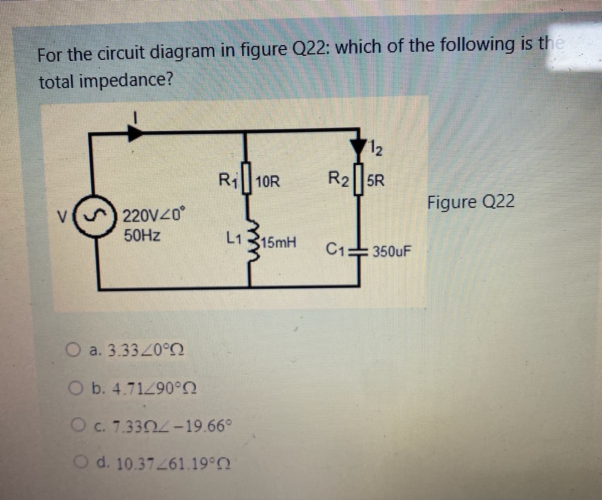
Transcribed Image Text:For the circuit diagram in figure Q22: which of the following is the
total impedance?
12
Ri 10R
R2||5R
Figure Q22
V
220V40
50HZ
L1 315mH
C1=350uF
O a. 3.33/0°
O b. 4.71290°2
O c. 7.3304-19.66°
O d. 10.37261.19°2
Expert Solution
This question has been solved!
Explore an expertly crafted, step-by-step solution for a thorough understanding of key concepts.

Step by step
Solved in 2 steps with 1 images

Knowledge Booster


Learn more about
Need a deep-dive on the concept behind this application? Look no further. Learn more about this topic, electrical-engineering and related others by exploring similar questions and additional content below.Recommended textbooks for you
Power System Analysis and Design (MindTap Course …
Electrical Engineering
ISBN:
9781305632134
Author:
J. Duncan Glover, Thomas Overbye, Mulukutla S. Sarma
Publisher:
Cengage Learning
Power System Analysis and Design (MindTap Course …
Electrical Engineering
ISBN:
9781305632134
Author:
J. Duncan Glover, Thomas Overbye, Mulukutla S. Sarma
Publisher:
Cengage Learning