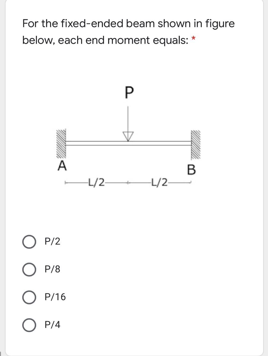
For the fixed-ended beam shown in figure below, each end moment equals: P A В L/2- L/2- P/2 O P/8 D/16


Q: A simply supported beam with span of 8 m is subjected to a counterclockwise moment at the left…
A: Given Data The length of the beam is:L=8m The yield strength of the steel beam is:Fy=248 MPa The…
Q: H.W 3_ Two aluminum alloy plates (2) are attached to the sides of a wooden beam (1) as shown in…
A:
Q: Determine the fixed-end moments (MA andMB) and fixed-end forces (RA and RB) for a beam oflength L…
A: given; lets take reaction force at A=RAlets take reaction force at B=RBweight density=q0AB=LAC=CB=L2…
Q: Defermine the internal normal force, shear force amd bending in the beam of the figure above (Fig.…
A:
Q: Beam ABCD represents a reinforcedconcretefoundation beam that supports a uniformload of intensity q1…
A: Given Load, q1 = 3500 lb/ft Length, L = 14 ft Find Shear force VB and bending moment MB
Q: A loaded, simply supported beam and its cross-section are shown in the figures below. 5 kN/m 20 mm:…
A: Solution:
Q: 2) Draw shear force and bending moment diagrams of the beam and find the maximum values of the shear…
A: Shear force calculations: ∑V=0 RA+5×6+20=0RA=-30-20RA=-50kNRA=50kN upwards Bending Moment…
Q: For the beam shown below ________ kN-m is the bending moment at its fixed end a. 0 b. -3 x 10⁵ c.…
A: To find the bending moment of the given cantilever beam; W = 1.5 kN/m L = 20 m
Q: P=80 N q=10 N/m B 100 느=40 m --=40 m 2 2
A: The given beam is shown below – Calculating reaction at support at A and B,
Q: Draw the shear-force and bending-momentdiagrams for a cantilever beam AB carrying a uniformload of…
A:
Q: H.W Draw shear force and bending moment diagrams for a cantilever beam as shown in Figure? I kN/m -…
A: Shear force diagram represents shear force at every section of the beam.. Shear force at any…
Q: 1. What is the load distribution in a beam whose moment distribution is as shov in the figure? 2 m A…
A: When the curve is parabolic in BMD then load is UDL When the curve is cubic in BMD then load is UVL…
Q: For the cantilever beam with uniformly distributed load shown in Figure find: d. The moment of…
A: Consider the given cantilever beam. Calculate the reaction at the fixed end. R=16 kN/m5 mR=80 kN…
Q: Anchor point of the beam given in the figure is fixed support and B point is movable support. Find…
A:
Q: A beam of length L=8.1 m is being designed to support a uniform load of intensity q = 9.7 kN/m. If…
A: Considering the beam, Let the center of the beam is at C, By symmetry bending moment at support is…
Q: Determine the maximum tensile bending stress of the entire beam (o max.ten.overall) in N/mm2, for…
A:
Q: A thin-walled closed section beam of constant wall thickness t has the cross-section shown in…
A: Given data as per question The thickness of the thin-walled closed section beam =t
Q: Consider a fixed beam under uniformly distributed load 'w' as shown in the figure below: w A B…
A: Data given -
Q: A simply supported beam is subjected to uniform distributed loading as shown in the figure. The…
A: Given L1 = L2 = 493 mm = 0.493 m w = 3000 N/m To determine position of the maximum bending moment…
Q: Consider the following uniformly loaded simple beam. The beam has a span length L = 2.5 m, the load…
A:
Q: Maximum bending moment: A simply supported rectangular beam that is 3000 mm long supports a point…
A: Write the given data. P=5000 NL=3000 mmb=127 mmh=254 mmd=254 mm
Q: 2. Curved block ABC, AB = parabolic curve and BC is straight in the horizontal direction. Point B is…
A: The Curved block ABC, AB = parabolic curve and BC is straight in the horizontal direction. Point B…
Q: The beam with triangular section L = 180 cm long shown in the figure is forced to bend with a…
A: Given: Maximum stress is 3600 daN/cm2. q=4.5 daN/cm Length of the beam is 180 cm. b=6 cm Factor of…
Q: The bending moment Mx affects the cross section of the beam given in Figure 4. Beam cross section…
A: I have given the answer in the steps below, Please consider UPVOTING this answer, it boosts my…
Q: Q: For the loaded simply supported beam shown in figure below, if the allowable bending stress is…
A:
Q: Q2: For the beam shown in figure below, find the bending stress of beam at point A. When I= 120*10*…
A: Bending equation is given as: MI=σy=ER where, M is the bending moment I is the moment of…
Q: aw the Normal Force Diagram. (b) Draw the shear force diagram. (c) Draw the bending moment…
A:
Q: N for Newton, m for meter, mm for millimeter, N/(mm^2) for Stress, mm^2 or m^2 for Area, mm^4…
A: Since we only answer up to 3 sub-parts, we’ll answer the first 3. Please resubmit the question and…
Q: 3-In the figure given below, P(load) and M(moment) effects from the mid point of the fixed beam from…
A: Both ends of a fixed or built-in beam are firmly fastened, ensuring that the slope at the ends…
Q: The homogeneous beam shown in the figure is suspended by a cable at point B and is pin supported at…
A:
Q: A simply supported beam is loaded as shown in the figure. Determine the slope and deflection at the…
A:
Q: Consider the simple beam in Figure 7 with two concentrated loads, where AB-BC=CD=4m: 6kN 12kN 12m…
A:
Q: 3. For the beam shown in Figure 3 determine the following:- 1. The second moment of area of the…
A: Shear force is the is the summation of all the forces either to the left of the section or to the…
Q: For the simply supported beam in figure, the shear force at midspan equals: 80 kN 80 kN 2 4 m Select…
A: Given, External force = 80 kN
Q: Two identical cantilever beams are supported, as shown in the figure, with their free ends in…
A:
Q: The beam in the figure below is made from three boards nailed together as shown, If the internal…
A:
Q: Q1 A cantilever beam AB of isosceles trapezoidal cross section has length L = 0.8 m, dimension bi =…
A: For solution refer below images.
Q: Rectangular Beam with height of cross section = 8" h=8" and width of cross section = 2" b=2" FIGURE…
A: Find the stress in the section.
Q: A cantilever beam of length 5m is loaded at the free end with a point load. The bending moment at…
A: Given data: The length of the beam is L = 5 m. The bending moment at the fixed end is M = 2.5 kN-m.…
Q: A beam AB with overhanging is 6 m in length and made from steel as shown in Figure 2. It is…
A: UVL Uniform varying load on the beam as shown in problem figure. This load is in increasing manner…
Q: 3-In the figure given below, P(load) and M(moment) effects from the mid point of the fixed beam from…
A:
Q: An overhanging beam is subjected to a partial uniform load w 26 kN/m and two pint loads P1 99 kN, P2…
A: Consider the free body diagram: Balancing forces in X direction:RA+RB+99=475+26*9RA+RB=610…
Q: Since beam M in the figure is under simple bending moment, A, B and C Calculate the bending stress…
A: Given data: Table and figure as shown above To determine: Bending stress and shear stress value at…
Q: Figure (a) shows a cantilever box beam that is subjected to a pure bending moment M=3kN.m about the…
A:
Q: Q: For the cantilever beam with uniformly distributed load shown in Figure find; a The maximum shear…
A: As per company policy, we are restricted to solve only the first three sub-part of one question at a…
Q: The beam AB, shown in Figure 1a, with length L = 4.5 m is subjected to a uniform distributed load w…
A: A beam is defined as a structural member subjected to transverse shear load during its…
Q: ter of the beam must be at least how many mm so that the amount of collapse that will occur at point…
A: We will find out the deflection at B due to point load and moment and equate it with permissible…
Q: Example 5: Draw the shear force and bending moment diagrams for the simply supported beam as shown…
A:
Q: Determine the equivalent distributed load associated with the beam shown in Figure Q4. Determine the…
A:

Step by step
Solved in 3 steps with 4 images


- Cantilever beam AB carries an upward uniform load of intensity q1from x = 0 to L/2 (see Fig. a) and a downward uniform load of intensity q from x = L/2 to L. Find q1in terms of q if the resulting moment at A is zero. Draw V and M diagrams for the case of both q and qtas applied loadings. Repeat part (a) for the case of an upward triangularly distributed load with peak intensity q0(see Fig. b). For part (b), find q0, instead of q1The cross section of a rectangular beam having a width b and height h is shown in part a of the figure. For reasons unknown to the beam designer, it is planned to add structural projections of width b/9 and height d/9 the top and bottom of the beam (see part b of the figure). For what values of d is the bending-moment capacity of the beam increased? For what values is it decreased?A beam ABC is fixed at end A and supported by beam DE at point B (sec figure). Both beams have the same cross section and are made of the same material. Determine all reactions due to the load P. What is the numerically largest bending moment in cither beam?
- Two identical, simply supported beams AB and CD are placed so that they cross each other at their midpoints (sec figure). Before the uniform load is applied, the beams just touch each other at the crossing point. Determine the maximum bending moments (mab)max* and (MCD)max beams AB and CD, respectively, due to the uniform load if the intensity of the load is q = 6.4 kN/m and the length of each beam is L = 4 m.The cross section of a sand wie h beam consisting of aluminum alloy faces and a foam core is shown in the figure. The width b of the beam is 8.0 in, the thickness I of the faces is 0.25 in., and the height hcof the core is 5.5 in. (total height h = 6.0 in). The moduli of elasticity are 10.5 × 10⁶ psi for the aluminum faces and 12.000 psi for the foam core. A bending moment M = 40 kip-in. acts about the z axis. Determine the maximum stresses in the faces and the core using (a) the general theory for composite beams and (b) the approximate theory for sandwich beams.A fixed-end beam AB of a length L supports a uniform load of intensity q (see figure). Beginning with the second-order differential equation of the deflection curve (the bending-moment equation), obtain the reactions, shear forces, bending moments, slopes, and deflections of the beam. Construct the shear-force and bending-moment diagrams, Labeling all critical ordinales.
- A fixed-end beam AB carries point load P acting at point C. The beam has a rectangular cross section (b = 75 mm, h = 150 mm). Calculate the reactions of the beam and the displacement at point C. Assume that E = 190 GPa.The compound beam shown in the figure consists of a cantilever beam AB (length L) that is pin-connected to a simple beam BD (length 2L). After the beam is constructed, a clearance c exists between the beam and a support at C, midway between points B and ZX Subsequently, a uniform load is placed along the entire length of the beam. What intensity q of the load is needed to close the gap at C and bring the beam into contact with the support?The hollow box beam shown in the figure is subjected to a bending moment M of such magnitude that the flanges yield but the webs remain linearly elastic. (a) Calculate the magnitude of the moment M if the dimensions of the cross section are A = 15 in., A] = 12.75 in., h = 9 in., and ey =7.5 in. Also, the yield stress is eY = 33 ksi. (b) What percent of the moment M is produced by the elastic core?
- What is the span length L of a uniformly loaded, simple beam of wide-flange cross section (see figure) if the maximum bending stress is 12,000 psi, the maximum deflection is 0.1 in., the height of the beam is 12 in., and the modulus of elasticity is 30 × 106psi? (Use the formulas of Example 9-1.)A beam with a channel section is subjected to a bending moment M having its vector at an angle 0 to the 2 axis (see figure). Determine the orientation of the neutral axis and calculate the maximum tensile stress et and maximum compressive stress ecin the beam. Use the following data: C 8 × 11.5 section, M = 20 kip-in., tan0=l/3. See Table F-3(a) of Appendix F for the dimensions and properties of the channel section.The cross section of a sandwich beam consisting of fiberglass faces and a lightweight plastic core is shown in the figure. The width b of the beam is 50 mm, the thickness I of the faces is 4 mm, and the height hcof the core is 92 mm (total height A = 100 mm). The moduli of elasticity are 75 GPa for the fiberglass and 1.2 GPa for the plastic. A bending moment M = 275 N · m acts about the z axis. Determine the maximum stresses in the faces and the core using (a) the general theory for composite beams and (b) the approximate theory for sandwich beams.