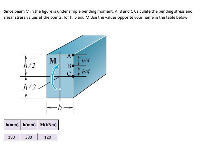
Since beam M in the figure is under simple bending moment, A, B and C Calculate the bending stress and shear stress values at the points. for h, b and M Use the values opposite your name in the table below. A I h/4 Be M h/2 C h/2 b(mm) h(mm) M(kNm) 180 380 120
Q: з KN/m 1,5 KN/m 1,5 KN/m B (m) 1,5 2,6
A:
Q: 1500 Ib/ft В A C 6000 lb – 4 ft → - 6 ft – Figure - 02
A: Let RA and RB are reactions at A and B Using equilibrium of forces in vertical and moment at A is…
Q: Shown below is a beam carrying a uniform load and two vertical forces at points B and D as shown in…
A: Find the shear force and bending moment equation and their diagrams
Q: Solve,
A: Uniform distributed load is acting for the distance "4m".load P=(20 kN/m)×4m=80 kN ;this load will…
Q: Given an overhanging beam loaded as shown in the figure. 40 KN 30 KN/m 10 KN-m 3m 2 m 2 m 1.1.…
A: (1.1) Draw the free-body diagram.
Q: Defermine the internal normal force, shear force amd bending in the beam of the figure above (Fig.…
A:
Q: The Figure shows a loading set up similar to that of the 'Bending in Beams' laboratory experiment. E…
A:
Q: A loaded, simply supported beam and its cross-section are shown in the figures below. 5 kN/m 20 mm:…
A: Solution:
Q: 01: For the beam ABCD subjected to the loading shown in figure below (B intemal hinge) (1) draw the…
A: AB:
Q: The cross-sectional dimensions of the beam shown in the figure are a = 4.6 in., b = 5.5 in., d = 4.4…
A:
Q: Draw Shear and Moment Diagrams for each of the beams below and find max bending stress. Every beam…
A:
Q: A beam of 8 m long, loaded with uniformly distributed load on the 4 m span CE with a concentrated…
A: The free body diagram of the beam is as follows: Calculate the moment about point d as follows:…
Q: For the beam shown below ________ kN-m is the bending moment at its fixed end a. 0 b. -3 x 10⁵ c.…
A: To find the bending moment of the given cantilever beam; W = 1.5 kN/m L = 20 m
Q: P=80 N q=10 N/m B 100 느=40 m --=40 m 2 2
A: The given beam is shown below – Calculating reaction at support at A and B,
Q: 5 kN/m M = 60 kN-m MAT o.com 2 m 2 m 1 m Figure P-426
A: Given: Uniform loading=5kN/m Moment (M)=60kNm
Q: A wood beam carries the loading shown in the figure. calculate the magnitude of the bending stress…
A:
Q: 3000 N/m (3) The beam AB shown in the figure supports a uniform load of intensity 3000 N/m acting…
A: Explanation: ◆ Before drawing SFD and BMD, we need to find the intensity of uniformly distributed…
Q: igid support geomet in the figure and parameter table. Find the equations for the shear and moment…
A: Given: The length of AB, L1 = 4 m The length of BC, L2 = 4 m The length of CD, L3 = 3 m The moment…
Q: The overhanging beam and its cross section is shown in figure (Attached) below; a) Calculate maximum…
A: Data given - overhanging beam with its cross section Udl = 20kN/m P = 20 kN Total length of the…
Q: 58 kN/m For the beam and loading shown in figure, answer the Hinge questions below -5.5 m- 254 mm 18…
A: Given data: The length of the cantilever having the uniformly distributed load is, L=5.5 m. The…
Q: For the beam shown in the figure in below A) Draw the shear force and bending moment diagram. B)…
A: A pin support will exert both horizontal and vertical components of reaction. The support B is pin…
Q: . For the beam shown, calculate (a) the maximum bending stress; and (b) the bending stress at a…
A:
Q: Calculate the shear force and bending moment for the beam subjected to the loads as shown in the…
A:
Q: QUESTION 1. Longitudinal and cross-sectional views of a beam are given in the figure below. (a) Draw…
A:
Q: The shear diagram of a beam is as shown in the figure. Solve for the maximum positive moment and…
A: Shear force is the force that makes the layers of beam undergo shear (sliding in vertically downward…
Q: The cross-sectional dimensions of the beam shown in the figure are a = 4.4 in., b = 4.9 in., d = 4.2…
A:
Q: A wood beam carries the loading shown in the figure. calculate the magnitude of the bending stress…
A:
Q: For the beam shown below, Find the bending stress at point A. 16 50 kN 22 + 3 m 3 m
A:
Q: Q: For the loaded simply supported beam shown in figure below, if the allowable bending stress is…
A:
Q: A beam of 8 m long, loaded with uniformly distributed load on the 4 m span CE with a concentrated…
A: Given dataSN = Student NumberTotal length fo the beam L = 8mBending moment = SN (kN)To draw the…
Q: The simply supported beam is subjected to the loading and has cross-sectional area as in the figure…
A: Draw a free-body diagram of a given beam. Apply force equilibrium in a vertical direction.…
Q: The cross-sectional dimensions of the beam shown in the figure are a = 4.5 in., b = 5.7 in., d = 4.7…
A:
Q: For the beam shown in the figure in below A) Draw the shear force and bending moment diagram. B)…
A: A pin support will exert both horizontal and vertical components of reaction. The support B is pin…
Q: A wood beam carries the loading shown in the figure. calculate the magnitude of the bending stress…
A:
Q: A simply supported beam carries a distributed load of 10 kN/m over a span of 5 m and a concentrated…
A: Given Data: udl intensity w=10 KN/m Span L=5 m Point loads =10 KN ,8 KN
Q: For the beam illustrated in the figure, find the locations and magnitudes of the maximum tensile…
A:
Q: For the beam shown below, determine the maximum bending stress in the beam. sketch the section…
A:
Q: 80 kN/m B 2 m -2 m-
A:
Q: Calculate the shear force V (in kN) and bending moment M (in kN - m) at a cross section located just…
A:
Q: Q3: Draw the shear force and bending moment diagrams for the loaded beam (shown (see figure below).…
A:
Q: For the fixed-ended beam shown in figure below, each end moment equals: P A В L/2- L/2- P/2 O P/8…
A: For the fixed-ended beam shown in figure below, each end moment equals: P/2 P/8 P/16 P/4
Q: A beam of 8 m long, loaded with uniformly distributed load on the 4 m span CE with a concentrated…
A:
Q: SKN | SKN A simply supported beam subjected to three point loads as shown in the Figure . Draw shear…
A:
Q: Analyze the simply supported beam shown in figure-6, by drawing its Shear Force and Bending Moment…
A:
Q: is three times larger than in steel shaft. Q1) For the section shown aside, if the bending stress at…
A:
Q: 5.3 The bending moment acting on the w 360 x 262 section is 460 kN- m. Find the maximum bending…
A: ANSWERING QUESTION 5.3 AS ASKED.
Q: 1. A simply supported beam with rectangular cross-section is loaded as shown in the figure. Draw the…
A:
Q: Draw shear force digam and bending moment digram for the following beam 300 N 500 N 800 N to A B 0.5…
A: The given loading system is a cantilever beam loading. Shear force is the force which makes the…
Q: The beam whose support and loading status is given in the figure, a) Draw the shear force diagram.…
A:
Q: Draw the shear and moment diagrams for the beam shown in figure below. Write down the name of this…
A:
Step by step
Solved in 3 steps
- A rectangular beam with semicircular notches, as shown in part b of the figure, has dimensions h = 120 mm and h1= 100 mm. The maximum allowable bending stress in the plastic beam is emix = 6 M Pa, and the bending moment is M = 150 N · m. Determine the minimum permissible width bminof the beam.The cross section of a sand wie h beam consisting of aluminum alloy faces and a foam core is shown in the figure. The width b of the beam is 8.0 in, the thickness I of the faces is 0.25 in., and the height hcof the core is 5.5 in. (total height h = 6.0 in). The moduli of elasticity are 10.5 × 10⁶ psi for the aluminum faces and 12.000 psi for the foam core. A bending moment M = 40 kip-in. acts about the z axis. Determine the maximum stresses in the faces and the core using (a) the general theory for composite beams and (b) the approximate theory for sandwich beams.Two identical, simply supported beams AB and CD are placed so that they cross each other at their midpoints (sec figure). Before the uniform load is applied, the beams just touch each other at the crossing point. Determine the maximum bending moments (mab)max* and (MCD)max beams AB and CD, respectively, due to the uniform load if the intensity of the load is q = 6.4 kN/m and the length of each beam is L = 4 m.
- A frame ABCD is constructed of steel wide-flange members (W8 x 21; E = 30 x ID6 psi) and subjected to triangularly distributed loads of maximum intensity q0acting along the vertical members (see figure). The distance between supports is L = 20 ft and the height of the frame is h = 4 ft. The members are rigidly connected at B and C. Calculate the intensity of load q0 required to produce a maximum bending moment of 80 kip-in. in the horizontal member BC. If the load q0 is reduced to one-half of the value calculated in part (a), what is the maximum bending moment in member BC? What is the ratio of this moment to the moment of 80 kip-in. in part (a)?The cross section of a bimetallic strip is shown in the figure. Assuming that the moduli of elasticity for metals A and B are EA=168 GPa and EB= 90 GPa, respectively, determine the smaller of the two section moduli for the beam. (Recall that section modulus is equal to bending moment divided by maximum bending stress.) In which material does the maximum stress occur?The hollow box beam shown in the figure is subjected to a bending moment M of such magnitude that the flanges yield but the webs remain linearly elastic. (a) Calculate the magnitude of the moment M if the dimensions of the cross section are A = 15 in., A] = 12.75 in., h = 9 in., and ey =7.5 in. Also, the yield stress is eY = 33 ksi. (b) What percent of the moment M is produced by the elastic core?
- A beam supporting a uniform load of intensity q throughout its length rests on pistons at points A, C and B (sec figure). The cylinders are filled with oil and are connected by a tube so that the oil pressure on each piston is the same. The pistons at A and B have diameter d1and the piston at C has diameter D2. (a) Determine the ratio of d2to d1so that the largest bending moment in the beam is as small as possible. Under these optimum conditions, what is the largest bending moment Mmaxin the beam? What is the difference in elevation between point C and the end supports?A rectangular beam with semicircular notches, as shown in part b of the figure, has dimensions h = 0,88 in. and h1 = 0.80 in. The maximum allowable bending stress in the metal beam is emax = 60 ksi, and the bending moment is M = 600 lb-in. Determine the minimum permissible width bminof the beam.A simple beam with a W 10 x 30 wide-flange cross section supports a uniform load of intensity q = 3.0 kips/ft on a span of length L = 12 ft (sec figure). The dimensions of the cross section are q = 10.5 in., b = 5.81 in., t1= 0.510 in., and fw = 0.300 in. Calculate the maximum shear stress tjuly on cross section A—A located at distance d = 2.5 ft from the end of the beam. Calculate the shear stress rat point Bon the cross section. Point B is located at a distance a = 1.5 in. from the edge of the lower flange.
- .20 Determine the plastic moment Mpfor beam having the cross section shown in the figure ey=210 MPa.Determine the maximum bending stress emaxdue to pure bending by a moment (M) for a beam having a cross section in the form of a circular core (see figure). The circle has diameter d and the angle ß = 60°. Hint: Use the formulas given in Appendix E, Cases 9 and 15..10 A built-up bourn supporting a condominium balcony is made up of a structural T (one half of a W 200 x 31.3) for the top flange and web and two angles (2 L 2 / b / 6.4. long legal back-lo-backl lot the bottom flange and web. as shown. The beam is subjected to a bending moment .1/ having its vector at an angle ft lo the z axis (see figure). Determine the or ion ta I ion of the neutral axis and calculate the maximum tensile stress ir, and maximum compressive stress tr. in ".he beam. .Assume that 9 = 30°andM = 15 kN · m. Use the numerical properties: c =4.111mm, c2 =4.169 mm, of = 134 mm, I, = 76 mm, A = 4144 mm 3 =3.88 X 106 mm 4, and = 34.18 X 10 mm 4.