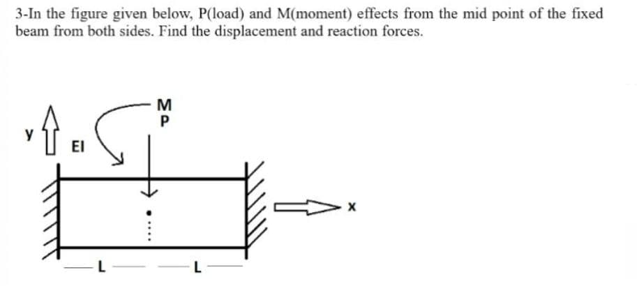
3-In the figure given below, P(load) and M(moment) effects from the mid point of the fixed beam from both sides. Find the displacement and reaction forces. y EI MP


Q: Find the bearing reaction forces of the beam in the figure.
A:
Q: Draw the shear-force and bending-moment diagrams for a simple beam as shown in Figure Q2 with a…
A:
Q: Calculate the shear force and bending moment for the frame subjected to the loads as shown in the…
A:
Q: A beam ABCD with a vertical arm CE is supported as simple beam at A and D as shown in the figure. A…
A: dear student please rate me positive Stay safe stay happy!
Q: he beam in Figure 1; (a) Draw the Normal Force Diagram. (b) Draw the shear force diagram.…
A: Given that , P=9KNtanθ=43θ=53.13°
Q: Let's consider a simple supported beam subjected to a triangular distributed load and a couple…
A:
Q: 50 kN/m 20 kN/m Q-1 For the beam loaded as shown in the figure, draw the shear force and bending A…
A: Given: To draw the shear force and bending moment diagram. NOTE: According to Bartleyby's policy we…
Q: A simply supported beam ABC is loaded by a vertical load P acting at the end of a bracket BDE(see…
A: The given diagram for the problem is ,
Q: G4//Draw shear and bending moment diagram as shown in figure. by graphical method. 132.5KN 122.5KN.m…
A: A pin support will exert both the horizontal and vertical components of a reaction. Let the support…
Q: shown in Figure 3(a) a roller support channel section as shown in Figure 3b). Determine the support…
A: Since you have posted a question with multiple subpart, so we will solve first three part for you.…
Q: The simple beam AB supports a triangular load of maximum intensityq0= 10 lb/in. acting over one-half…
A: Given that , In a simple beam AB , Triangular load of maximum intensity qo=10lb/in concentrated…
Q: The simply supported beam as shown in the figure supports a concentrated force of 30 kN at B and a…
A: Explanation: The stepwise procedure to solve this problem is shown in the following attached image:
Q: 4.An overhang beam is applied with a uniformly distributed load as shown in Figure Q4. a. Derive an…
A:
Q: La7 For the simply supported beam and the loading shown in the figure find the * Chinge forces (B)…
A: It is required to determine support reaction force
Q: Q 2 : The cantilever beam in Figure carries a triangular load. The intensity of which varies at the…
A:
Q: 5N 0.5 N/m B 6 m.- - 6 m. - 6 m. - 6 m.- 1. A force of 5 N acts from point D on the beam carrying a…
A:
Q: For the beam shown in Figure 1. A. Find the reaction at support A (RA) B. Find the reaction at…
A:
Q: The simply supported beam in the figure is loaded by the counterclockwise Co at B. Draw the shear…
A: To draw SFD and BMD
Q: Anchor point of the beam given in the figure is fixed support and B point is movable support. Find…
A:
Q: A simply supported beam AB supports a trapezoid ally distributed load (see figure). The intensity of…
A: →First calculating Reactions:∑MB=0⇒RA(4)−25(4)42−25×42×2×43=0⇒RA=83.33kN+↑…
Q: For the beam shown in the figure below: (i) (ii) (iii) Determine all the support reactions. Draw the…
A: Given:- Beam with different loading and supports. C and E are hinges B, F, and G are roller A is pin…
Q: For the rod loaded as shown in figure, the maximum bending moment is 5 kN-m. AB=BC=CD= 1m. The value…
A: The bending moment due to force of 2 kN can be determined as,
Q: Consider the circular bent rod with diameter 20 mm. The free-end of the bend is subjected to loads…
A:
Q: A cantilever beam AB with a built-in restraint at end A is subjected to a combination of loads as…
A:
Q: 4.3-4 Calculate the shear force Vand bending moment M at a cross section located just right of the 4…
A:
Q: Question 4 For the beam shown in the figure below: (i) (ii) (iii) Determine all the support…
A: To calculate the reactions,First seperating the beam segments from hinge,The equilibrium equations…
Q: 4.5-3 /Draw the shear-force and bending-moment diagrams for a cantilever beam AB carrying a uniform…
A:
Q: Q For the beam shown in the figure do the following:- 1. Draw the shear force and bending moment…
A:
Q: A simply supported beam of length 6m carries two point loads of magnitude 1KN and 4KN at a distance…
A: To determine the reaction at both the supports, we must apply the statics equations: Summation of…
Q: 7) Consider the beam in the figure below. Take w=50 kN/m. The 40 kN force makes an angle of 60…
A:
Q: Express shear force V and bending moment M as functions of arbitrary position x along the axis for…
A:
Q: Calculate the shear force Vand bending moment Mata cross sectionjust to the right of the 800 lb load…
A:
Q: 30 kN/m 10 kN 10 kN/m 3.5 m60 B 225 kN-m 30 kN/m |2.5 m- 6 m 9 m
A:
Q: 2. For the structural beam loaded and supported as shown in Figure 2, (a) Draw a free body diagram…
A:
Q: Problem 2: For the beam shown in Figure A. Find the reaction at support B (RB) B. Find the reaction…
A: Given Data
Q: 3. For the beam shown below, let wo = 90 N/m and w1 50 N/m. %D Wo | A B -2 m-2 m+3 m 3 m- -2 m…
A:
Q: Beam ABCDE as in Figure Q1 is pin connected at A and roller supported at E. (a) Sketch the free body…
A:
Q: 4.5-6 The simple beam AB shown in the figure receives a concentrated load P and a clockwise dominant…
A:
Q: The beam AB in the figure supports a load which varies from an intensity of 50 KN per linear meter…
A: This numerical is related to the strength of material portion. Concept is used Convert actual…
Q: Q4. A freely supported light uniform beam of length 8 metres is subject to the loading shown in…
A: For solution refer below images.
Q: For the beam AB, an angled force and constant load profile is applied. The force is angled 45° to…
A:
Q: Figure Q3a shows a simply supported beam AB with support reactions RA and RB. Two point loads F1 =…
A: Before drawing shear force or bending moment diagram, first of all we have to find the external…
Q: points A, B and D, respectively, as shown in the figure. A uniformly distributed loac of 4 kN/m…
A:
Q: Let's consider a simple supported beam subjected to a triangular distributed load and a couple…
A: Answer is M(x) = -83.3 X3 - 166.7 X ( N.m)
Q: Problem 4: A barge shown in the figure carries 290kN/m and 580KN/m loads. 3m 6m Зт 580 kN/m a. Find…
A: The given beam is as shown below, Let the upward load acting on the beam is w, (a) Balancing…
Q: 4- The value of reaction acting on point B, for the simply supported beam shown in Figure (1) below…
A: Solution:
Q: The beam AB in the figure supports a load which varies from an intensity of 50 KN per linear meter…
A:
Q: Q4: For the simply surported beam loaded as in the figure. " 10 kN/m 1. Find the beam deflection…
A:

Step by step
Solved in 2 steps with 3 images

- A simply supported beam ABC is loaded at the end of a bracket BDE (see figure). Draw axial-force, shear-force, and bending-moment diagrams for ABC.A cable with force P is attached to a frame at D and runs over a frictionless pulley at A Find expressions for shear force V and moment M at x = L/3 of beam AB.Repeat 1.3-9 but use the method of sections go find member forces in AC and BD.
- A beam ABCD with a vertical arm CE is supported as a simple beam at .1 and D (see figure). A cable passes over a small pulley that is attached to the arm at E. One end of the cable is attached to the beam at point B. The tensile force in the cable is 1800 lb. Draw the shear-Force and bending-moment diagrams for beam A BCD. Note: Disregard the widths of the beam and vertical arm and use centerline dimensions when making calculations. Repeat part (a) if a roller support is added at C and a shear release is inserted just left of C (see figure part b).The simple beam ACE shown in the figure is subjected to a triangular load of maximum intensity q0= 200 lb/ft at a = 8 ft and a concentrated moment M = 400 Ib-ft at A. Draw the shear-force and bending-moment diagrams for this beam, Find the value of distanced that results in the maximum moment occurring at L/2. Draw the shear-force and bending-moment diagrams for this case. Find the value of distance a for which Mmaxis the largest possible value.A beam ABCD with a vertical arm CE is supported as a simple beam al A and D (see figure part a). A cable passes over a small pulley that is attached to the arm at E. One end of the cable is attached to the beam at point B. (a) What is the force P in the cable if the bending moment in the beam just lo the left of point C is equal numerically to 640 lb-ft? Note: Disregard the widths of the beam and vertical arm and use centerline dimensions when making calculations. (b) Repeat part (a) if a roller support is added at C and a shear release is inserted just left of C (see figure part b).
- Beam ABC is supported by a tie rod CD as shown. Two configurations are possible: pin support at A and downward triangular load on AB or pin at B and upward load on AB. Which has the larger maximum moment? First, find all support reactions; then plot axial force (N), shear (V), and moment (M) diagrams for ABC only and label all critical N, V, and M values. Label the distance to points where any critical ordinates are zero.Find expressions for shear force V and moment M at mid-span of beam AB in terms of peak load intensity q0and beam length variables a and L Let a = 5L/b.Find support reactions at 4 and Band then use the method of joints to find all member forces. Let b = 3 m and P = 80 kN.
- Find support reactions at A and D and then calculate the axial force N, shear force V, and bending moment M at mid-span of AB. Let L = 14 ft, q0 = 12 lb/ft, P = 50 lb. and = 300 lb-ft.Frame ABC has a moment release just left of joint B. Find axial force N, shear force V, and moment M at the top of column AB. Write variables N, V, and M in terms of variables P and L.Repeat Problem 6.4-14 but use the configuration of channel shapes and loading shown in the figure. Use P = 250 N.