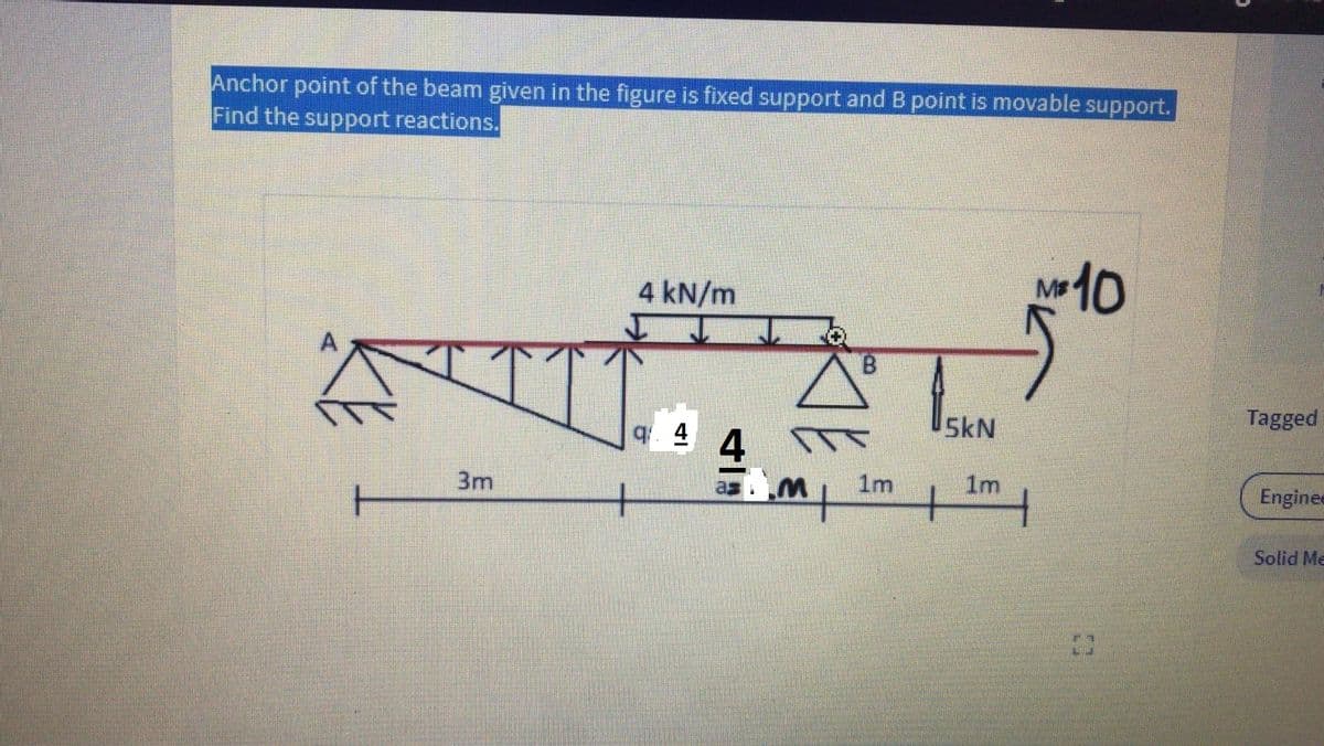
Anchor point of the beam given in the figure is fixed support and B point is movable support. Find the support reactions. a=4 q=4 M=10


Q: he beam shown in the figure carries a distributed load and also a concentrated load. Taking into…
A: Part A) Determine the reaction at support by apply equilibrium condition
Q: The horizontal beam ACB with the cross section dimension (width = b) (height = h) is shown on the…
A: INTRODUCTION: This is a basic problem of joints and struts and explained with details of free body…
Q: Question 1: A simply supported beam is shown in the figure below which is used to carry a load P.…
A:
Q: Anchor of the beam given in the figure is built-in support, B point is movable support and G joint.…
A: Let the reactions at fixed support 'A' be: RAH , RAV , MA. Let the reactions at pin joint 'G' be:…
Q: For the beam in the figure that has as data: P = 24 kN, w = 12 kN /m and L = 8 m, El = cte. Applying…
A: According to the given details in the question. P = 24kN , E = 200 GPa = 200x106 kN/m2 , I = 5x10⁸…
Q: In the figure, aluminum [E = 72 GPa] links (1) and (2) support rigid beam ABC. Link (1) has a…
A:
Q: The constructed shear force diagram (SFD) for the simply supported beam with a Triangle distributed…
A:
Q: 4.44 For the 8-in. I-beam shown in figure below, compute the maximum transverse shear stress (use…
A: First let us determine the moment of inertia of the section Moment of inertia about neutral axis =…
Q: H.W. 3 / Find the reactions of the simply supported beam shown in Figure below 200 lb 400 lb-ft A |B…
A: Given RAy=200 lb
Q: The cantilever beam in the figure has a fixed support at A and is under the actions of a uniformly…
A:
Q: 60 kN/m 20 N 30 kN 10 kN/m
A:
Q: A PB y Pc W1 В W2 H A B C L1 L2
A:
Q: situation; a) Maximum normal stress
A:
Q: In the figure, aluminum [E = 75 GPa] links (1) and (2) support rigid beam ABC. Link (1) has a…
A:
Q: In the figure, aluminum [E = 60 GPa] links (1) and (2) support rigid beam ABC. Link (1) has a…
A:
Q: In figure, there is a single rigid beam supported at two points: A and B. 250 N 2 m Calculate the…
A:
Q: 10.4-13 Beam ABC is fixed at support A and rests (at point B) upon the midpoint of beam DE (see the…
A: The deflection diagram of the beam without considering beam DE is given as, The maximum deflection…
Q: H.W. 2 / Find the reactions of the simply supported beam shown in Figure below 300kN 30kNm 15kNm .B…
A: Answer: (a) The reactions at the hinge support A: (RA)x = 180 kN ; (RA)y = 165 kN. (b) The reactions…
Q: The figure shows a cantilever consisting of steel angles size 100 x 100 x 12 mm mounted back to…
A: given data; ⇒w=1KN/mF=2.5KN⇒OA=2m⇒OB=3m⇒AB=1m
Q: Q/ For the beam shown in the figure below, find deflection and rotation at point B. EI=12000 kN.m2.…
A:
Q: The homogeneous beam shown in the figure is suspended by a cable at point B and is pin supported at…
A:
Q: H.W. 1 / Find the reactions of the simply supported beam shown in Figure below 6 kN/m 20 kN A B Fig.…
A:
Q: For the prismatic beam attached to the load shown in the figure, get the reactions and show them in…
A: .
Q: Problem No. 1 Determine the reactions for the beam shown in Figure below, 1300 N 1800 N 1460 N/m…
A: Given Data⇒ Beam
Q: 10.4-13 Beam ABC is fixed at support A and rests (at point B) upon the midpoint of beam DE (see the…
A: The general expression for deflection at any point x in a cantilever beam in that the load P is…
Q: A beam is subjected to a distributed load and a concentrated force F (magnitude 400 N) at the end of…
A:
Q: Problem 3. Problem. The upper beam in figure is supported by a reaction R3 at D and a roller at C…
A:
Q: 10.4-29 A propped cantilever beam is loaded by a triangular distributed load from A to C (see…
A:
Q: The homogeneous beam shown in the figure is suspended by a cable at point B and is pin supported at…
A:
Q: For the beam shown in the figure if W- 14 KN/m. Determine the following: 14. The normal force at…
A: (14)
Q: 2: For the beam shown in Fig.(2), find the reaction forces at supports A and B respectively? %) 20…
A:
Q: Find the external reactions at supports A (hinge) and B (roller) for the beam shown in the figure.…
A: To find: The external reaction supports A and B. FBD: The free body diagram shown below:
Q: cross-section, simply supported at locations A and C. A uniformly distributed load of 10 kN/m is…
A: Since you have asjed a multi-question, thus according to our guidelines we can provide you the…
Q: The figure shows a propped up horizontal cantilever beam carrying a 1kN load at the end. The shear…
A: To determine the value of shear force in segment BC.
Q: In the figure, one end of a uniform beam of weight 130 N is hinged to a wall; the other end is…
A: To find: The tension in the wire. Given: The weight of the one end of the beam is hinged to the wall…
Q: The overhanging beam is supported by a pin at A and the two-force strut BC as shown in Figure Q4.1.…
A: Now draw the free body diagram for the above problem.
Q: For the fixed-ended beam shown in figure below, each end moment equals: P A В L/2- L/2- P/2 O P/8…
A: For the fixed-ended beam shown in figure below, each end moment equals: P/2 P/8 P/16 P/4
Q: Question 1) In the beam whose loading condition is given in the figure, F force F= 79 kN, w1…
A:
Q: Problem 3: For the beam shown in Figure A. Find the reaction at support B (RB) B. Find the reaction…
A:
Q: A propped cantilever beam AB of a length L carries a concentrated load P acting at the position…
A: There are three unknowns (RA, RB, and Rc) and only two equations. This is a statistically…
Q: The hollow circle cross section of the simply supported beam shown in the figure. Find the maximum…
A: For solution refer below images.
Q: The beam AB, shown in Figure 1a, with length L = 4.5 m is subjected to a uniform distributed load w…
A: A beam is defined as a structural member subjected to transverse shear load during its…
Q: H.W. 4 / Find the reactions of the simply supported beam shown in Figure below 50 kN 30 KN/m Int.…
A: As per our guideline we suppose to answer only one question. Kindly repost other questions as a…
Q: A beam weighing 50 kg is attached to a pin at C and supported by a steel cable OA with Young's…
A: 1) Free body diagram of the given beam is drawn below 2) To find Tension in the steel cable OA we…
Q: H.W. 4 / Find the reactions of the simply supported beam shown in Figure below 50 kN 30 kN/m Int.…
A:
Q: please answer the question
A: MAB=-400×108=-500 kN-mMBA=500 kN-mMBC=30×10212=30×10012=-250 kN-mMCB=250 kN-m
Q: . A homogeneous rod of constant cross section is attached to unyielding supports. It carries an…
A:
Anchor point of the beam given in the figure is fixed support and B point is movable support. Find the support reactions.
a=4 q=4 M=10

Step by step
Solved in 2 steps with 2 images


- The cantilever beam AB shown in the figure has an extension BCD attached to its free end. A force P acts at the end of the extension. Find the ratio aiL so that the vertical deflection of point B will be zero. Find the ratio aiL so that the angle of rotation at point B will be zero.The wing of a small plane is represented by a simplified prismatic cantilever beam model acted on by the distributed loads shown in the figure. Assume constant El = 1200kN-m~, Find the tip deflection and rotation at B.A simple beam AB supports two concentrated loads P at the positions shown in the figure. A support C at the midpoint of the beam is positioned at distance d below the beam before the loads are applied. Assuming that d = 10 mm, L = 6m, E = 200 G Pa, and I = 198 x 106 mm4, calculate the magnitude of the loads P so that the beam just touches the support at C.
- A two-span beam with spans of lengths L and L/3 is subjected to a temperature differential with temperature T1on its upper surface and T2on its lower surface (see figure). Determine all reactions for this beam. Use the method of superposition in the solution. Assume the spring support is unaffected by temperature. What are the reactions when k ?A beam made up all woun equal leg angles is subjected to a bending moment M having its vector .u an angle (i) lo lire axis (see figure paria). (a) For the position shown in lire figure, determine lire orienlalion of lire neulral axis and calculate lire maximum tensile s'av-s ir, and maximum compressive stress (b) The two angles are now inverted and attached back-lo-back lo lorn, a lintel beam that supports two courses of brick facade i see figure part b). Find the new orientation of the neutral axis and calculate the maximum tensile slress r. a::d maximum compressive s'avsrr . in I he beam using 6 = 30° and M = 30 kip-in.A framework A BCD is acted on by force P at 2L/3 from 8(see figure). Assume that 7f/is constant. Find expressions for reactions at supports B and C. Find expressions for angles of rotation at A, B* C, and D. Find expressions for horizontal deflections èAand ôD. If length LAB= L i 2, find length LCDin terms of L for the absolute value of the ratio
- A simply supported wooden I-beam with a 12-ft span supports a distributed load of intensity q = 90 lb/ft over its length (see figure part a). The beam is constructed with a web of Douglas-fir plywood and flanges of pine glued to the web, as shown in the figure part b. The plywood is 3/8 in. thick: the flanges are 2 in, × 2 in, (actual size). The modulus of elasticity for the plywood is 1,600,000 psi and for the pine is 1,200,000 psL Calculate the maximum bending stresses in the pine flanges and in the plywood web. What is q, if allowable stresses are 1600 psi in the flanges and 1200 psi in the web?A temporary wood flume serving as a channel for irrigation water is shown in the figure. The vertical boards forming the sides of the flume are sunk in the ground, which provides a fixed support. The top of the flume is held by tic rods that are tightened so that there is no deflection of the boards at that point. Thus, the vertical boards may be modeled as a beam AB, supported and loaded as shown in the last part of the figure. Assuming that the thickness t of the boards is 1,5 in., the depth d of the water is 40 in., and the height h to the tie rods is 50 in., what is the maximum bending stress in the boards? Hint: The numerically largest bending moment occurs at the fixed support.A C 200 x 17.1 channel section has an angle with equal legs attached as shown; the angle serves as a lintel beam. The combined steel section is subjected to a bending moment M having its vector directed along the z axis, as shown in the figure. The cent roi d C of the combined section is located at distances xtand ycfrom the centroid (C1) of the channel alone. Principal axes yl and yvare also shown in the figure and properties Ix1,Iy1and 0pare given. Find the orientation of the neutral axis and calculate the maximum tensile stress exand maximum compressive stress if the angle is an L 76 x 76 x 6.4 section and M = 3.5 kN - m. Use the following properties for principal axes for the combined section:/^, = 18.49 X 10⁶ nrai4,/;| = 1.602 X 106 mm4, ep= 7.448*(CW),_r£ = 10.70 mm,andvf= 24.07 mm.
- A framework A BCD is acted on by counterclockwise moment M at A (see figure). Assume that Elis constant. Find expressions for reactions at supports B and C Find expressions for angles of rotation at A, 5, C, and Z). Find expressions for horizontal deflections SÂand SD, If length LA3= L12, find length LCDin terms of L for the absolute value of the ratio |sysj=i.Segments A B and BCD of beam A BCD are pin connected at x = 4 m. The beam is supported by a sliding support at A and roller supports at C and D (see figure). A triangularly distributed load with peak intensity of SO N/m acts on EC. A concentrated moment is applied at joint D. (a) Find reactions at supports A, C, and D. (b) Find internal stress resultants N, Y, and Mat x = 5m. (c) Repeat parts (a) and (b) for die case of the roller support at C replaced by a linear spring of stiffness kr™ 200 kN/m (see figure).Beam ABC is fixed at support A and rests (at point B) upon the midpoint of beam DE (see part a of the figure). Thus, beam, ABC may be represented as a propped cantilever beam with an overhang BC and a linearly elastic support of stiffness k at point B (see part b of the figure). The distance from A to B is L = 10 ft, the distance from B to C is L/2 = 5 ft, and the length of beam DE is L = 10 ft. Both beams have the same flexural rigidity EI. A concentrated load P = 1700 lb acts at t lie free end of beam ABC. Determine the reactions RA, RB+ and MAfor beam ABC. Also, draw the shear-force and bending-moment diagrams for beam ABC, labeling all critical ordinates.