For the overhang beam shown below, (a) draw the free body diagram of the beam, (b) draw the shear and moment diagrams, (c) find moment of inertia of its cross-section, (d) determine the
For the overhang beam shown below, (a) draw the free body diagram of the beam, (b) draw the shear and moment diagrams, (c) find moment of inertia of its cross-section, (d) determine the

Mechanics of Materials (MindTap Course List)
9th Edition
ISBN:9781337093347
Author:Barry J. Goodno, James M. Gere
Publisher:Barry J. Goodno, James M. Gere
Chapter6: Stresses In Beams (advanced Topics)
Section: Chapter Questions
Problem 6.8.1P: A simple beam with a W 10 x 30 wide-flange cross section supports a uniform load of intensity q =...

Related questions

Question
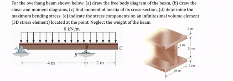
Transcribed Image Text:For the overhang beam shown below, (a) draw the free body diagram of the beam, (b) draw the
shear and moment diagrams, (c) find moment of inertia of its cross-section, (d) determine the
maximum bending stress. (e) indicate the stress components on an infinitesimal volume element
(3D stress element) located at the point. Neglect the weight of the beam.
8 kN/m
2 cm
em
A
C
25 em
B
4 m
2 m
2 cm
20 cm
Expert Solution
This question has been solved!
Explore an expertly crafted, step-by-step solution for a thorough understanding of key concepts.

Step by step
Solved in 5 steps with 5 images

Knowledge Booster


Learn more about
Need a deep-dive on the concept behind this application? Look no further. Learn more about this topic, mechanical-engineering and related others by exploring similar questions and additional content below.Recommended textbooks for you
Mechanics of Materials (MindTap Course List)
Mechanical Engineering
ISBN:
9781337093347
Author:
Barry J. Goodno, James M. Gere
Publisher:
Cengage Learning
Mechanics of Materials (MindTap Course List)
Mechanical Engineering
ISBN:
9781337093347
Author:
Barry J. Goodno, James M. Gere
Publisher:
Cengage Learning