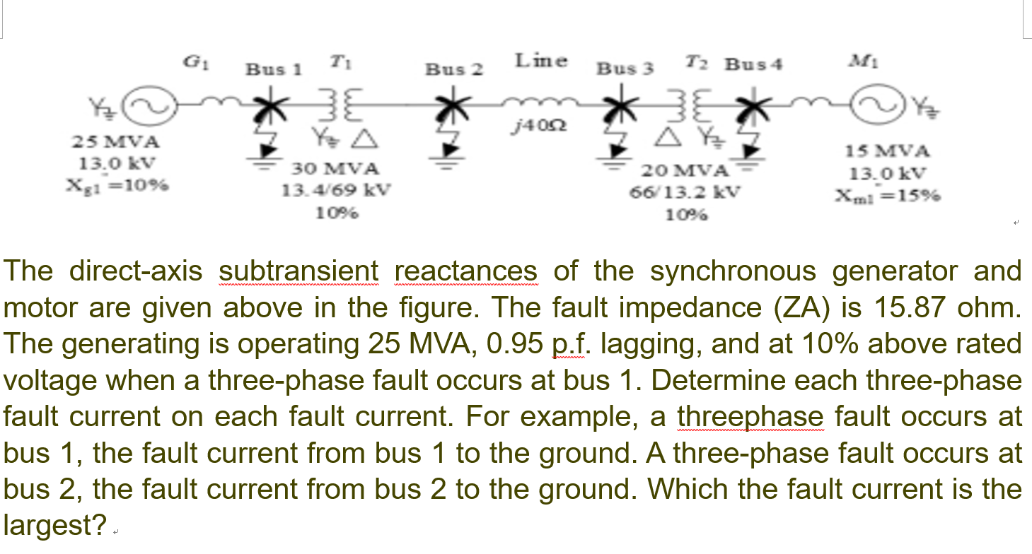
G1 Bus 1 Bus 2 Line Bus 3 T2 Bus4 M1 j402 25 MVA Ye A 13.0 kV Xg1 =10% зо мVA 13.4/69 kV 20 MVA 66/13.2 kV 15 MVA 13.0 kV Xmi =15% 10% 10% e direct-axis subtransient reactances of the synchronous generator and otor are given above in the figure. The fault impedance (ZA) is 15.87 ohm ie generating is operating 25 MVA, 0.95 p.f. lagging, and at 10% above rate Itage when a three-phase fault occurs at bus 1. Determine each three-phase ult
Q: 2. A 100 MVA, 18 kV generator, with per unit reactance of X”d = 0.19, X’d = 0.26, and Xd = 1.3 is…
A: In this question we need to find the initial symmetrical rms current in the line on the low voltage…
Q: a) Draw the sequence network and calculate the sub-transient fault current for a dead short circuit…
A:
Q: Three single-phase two-winding transformers, each rated 400 MVA, 13.8/ 199.2 kV, with leakage…
A:
Q: The sample power system subjected to three phase fault at bus 4. The system values are given below…
A: Find explanation below
Q: Q6/ A 3-phase, 50Hz synchronous generator having H=6 MJ/MVA is delivering power of 1.0 P.U to…
A: Critical clearing angle:- It is load angle at which fault is clear and system will stable, without…
Q: .A 33 KV line has a resistance of 4 ohm and reactance of 16 ohm respectively. The line is connected…
A: Given R=4 ohm X=16 ohm Let 10000 KVA be the base KVA Reactance of generator 1 Xg1=10 %…
Q: Q5: A generator is connected through a transformer to a synchronous motor. Reduced to the same base,…
A:
Q: Q5: A SL-G fault occurs on the low voltage side of a transformer that connects a motor to a…
A: Given data for generator, Given data for motor,
Q: pecified in per unit. For generators, assume Z* =Z` =j0.2, Z° = j0.05 For transformers, assume Z' =…
A:
Q: Question 1 A Y-connected synchronous generator has sequence reactance of Xo = 0.1pu; X1 = 0.22pu and…
A: A Y-connected generator has the sequence reactance of X0 = 0.1pu, X1 = 0.22pu, X2 = 0.36pu. Now, the…
Q: Q1/ Two generators are interconnected by a reactor of I Ohm reactance per phase. The estimated short…
A: multiple questions As per our guidlines we are supposed to do the first question if a student asks…
Q: The symmetrical fault occurs in the terminals of the synchronous generator. Find the direct axis…
A:
Q: 6. A 3 phase fault occurs at point F as shown in figure. Determine the critical clearing angle for…
A: Given figure, 3 phase fault occurs at point F as shown in the figure. The generator is delivering…
Q: For the network shown in the figure below, all reactances are in p.u. to a base of 100MVA and 13.8…
A: The power system is a network consist of power generation, transmission, and distribution. Power…
Q: Figure shows a sample power system network and Zpus Matrix elements. For a solid three phase fault…
A: Note: Here line impedance as well as Z bus matrix impedance are given We are going to solve the…
Q: symmetrical fault occurs in the terminals of the synchronous generator. Find the direct axis…
A: Find the symmetrical fault current Total Reactance? If the armature Reactance Xa 7.4ohm Leakage…
Q: The one-line diagram of a simple power system is shown in Figure 9.20. Each generator is represented…
A:
Q: The total instantaneous power absorbed by a three-phase motor (under balanced steady-state…
A: Consider the instantaneous voltage across phase a and the neutral terminal is given by:
Q: Problem #2: A transformer is fed from a 100 MVA, 18 kV generator via a 5-cycle breaker. Generator…
A: Given S =100 MVA V =18 KV Xd'' =18%Xd' =25%Xd =120%
Q: 1. A 100-MVA, 18-KV generator is connected to a transformer. The generator has reactances of 19%,…
A:
Q: The single-line diagram of a three-phase system is given in Figure 3. The three-phase generator is…
A: Given: The ratings of each element are as follows: Generator-4.16 MVA, 2.4 kV, 1000 A.Transformer…
Q: (b) A 50 Hz synchronous generator with inertia constant H = 6.2 MJ/MVA is connected to an infinite…
A:
Q: or A 25 MVA, 13.2 KV, alternator with solidly grounded neutral has a sub transient reactance of…
A: Given: A alternator in which S=25MVAVl=13.2KVXd''=0.025puX2=0.35puX0=0.10puZf=0pu Fault current is…
Q: Figure below shows a power system where load at bus 5 is fed by generators at bus 1 and bus 4. The…
A: When line L1 has length =100 km, fault current for fault at bus 5 is =2530 A When line L1 reduced to…
Q: 1. The open circuit characteristic of a 3-phase 10 MVA, 13 kV, 50 Hz, Star connected synchronous…
A: The values of saturated synchronous impedance do not change but vary in sensitivity and strength…
Q: 3. A 100 MVĂ, 33KV 3-phase alternåtör current are as under: 3-phase fault-2000A, Line to Line…
A: Please refer the attached images for the complete answer..
Q: Three 15MVA, 30kV synchronous generators A, B, and C are connected via three reactors to a common…
A: A synchronous generator is called an alternator; in an alternator, the rotating part is the field…
Q: A 1000-MVA 20-kV, 60-Hz three-phase generator is connected through a 1000-MVA 20-kV A/345-kV Y…
A: Three AC single-phase generators make up an AC three-phase generator. These generators are taken two…
Q: In a short circuit test on 132 kV, 3-phase system, the breaker gives the following results: Power…
A:
Q: The severity of line-to-ground and 3-phase faults at the terminals of an unloaded star connected…
A: Given, Terminal voltage, E = 1 pu Positive, negative, and zero sequence reactance is X1=X2=j0.35 pu…
Q: Q1a Voltage control – fault level • A load bus (bus-L) is suppling from two different buses A & B…
A:
Q: A 3-phase synchronous generator, rated 16 kV and 200 MVA, has negligible losses and synchronous…
A: Internal voltage E = Vt + IZ Where I is current And Z is impedance
Q: Figure below shows a power system where load at bus 5 is fed by generators at bus 1 and bus 4. The…
A: 1) When base voltage is changed to 11 kV, change in fault current ? 2)
Q: capacitors will supply reactive VAR during peak load condition and consumes reactive VARs during…
A: 1.Booster Transformer:-It is used at the end of a power line or at the intermediate position to…
Q: A synchronous generator of 100 MVA, 22 kV, and 0.25 pu transient reactance supplies a motor of 50…
A:
Q: A radial power system network is shown in figure below, a three phase balanced fault occurs at F.…
A:
Q: The 60 mile, 115 kV line GH (Figure P12.8) is operating with the voltages at each end 30° out of…
A:
Q: The zero sequence currents of a generator for line to ground fault is j2.4 p.u. then the current…
A:
Q: 3) The single-line diagram of a three-phase system is given in Figure 3. The three-phase generator…
A: Since you have asked multiple questions in a single request, we will be answering only the first…
Q: (b) A 50 Hz synchronous generator with inertia constant H = 6.2 MJ/MVA is connected to an infinite…
A:
Q: A three-phase synchronous generator produces 10 MVA power under a rated voltage of 10 kV. Zero…
A: Hello. Since your question has multiple sub-parts, we will solve the first three sub-parts for you.…
Q: Consider the system shown in the single-line diagram of Figure (3). All reactances are shown in per…
A: Three phase fault is symmetrical fault, hence fault study can be done on per phase basis. All the…
Q: 9. Four identical alternators each rated for 20 MVA, 11 KV have a subtransient reactance of 164 are…
A:
Q: A three-bus power system has generators at buses 1 and 2 with per unit subtransient reac- cances…
A: “Since you have asked multiple question, we will solve the first question for you. If you want any…
Q: A star connected 3-phase 10 MVA, 6.6 kV alternator is protected by circulating current protection,…
A: In this question , we will find value of earthing resistance required if 85% of stator winding is…
Q: A three-phase fault with fault impedance of j 0.12 pu occurs at bus 2. Find the fault current and…
A: In this question we need to find a fault current and bus voltage during fault.
Q: (b) A 30000 kVA, 13.8 kV generator with X = 18% is connected to a bus which supplies two identical…
A: Generator data Sb= 30000 kVA Vb=13.8 kV Xd'' =18 % Motor data Vb= 7 kV Sb=6000 kVA Xd'' =25 %
Q: The synchronous generator in Figure 2 is operating at rated MVA and at . PU 5% above rated voltage…
A: Given The synchronous generator in Figure 2 is operating at rated MVA and at 5% above rated voltage…
Q: A 100 MVA, 20 kV, 30 generator is operated with an internal voltage of 1.0 p.u. Assume a solid 3ộ…
A: Given data Xd''=0.15Xd'=0.24Xd=1.05Td''=0.038 sTd'=2.0 sTA=0.36 s General expression of ac fault…
Step by step
Solved in 5 steps with 11 images
- Equipment ratings for the five-bus power system shown in Figure 7.15 are as follows: Generator G1:    50 MVA, 12kV, X=0.2 per unit Generator G2: 100 MVA, 15 kV, X=0.2 per unit Transformer T1: 50 MVA, 10 kV Y/138kVY,X=0.10 per unit Transformer T2: 100 MVA, 15 kV /138kVY,X=0.10 per unit Each 138-kV line: X1=40 A three-phase short circuit occurs at bus 5, where the prefault voltage is 15 kV. Prefault load current is neglected. (a) Draw the positive-sequence reactance diagram in unit on a 100-MVA, 15-kV base in the zone of generator G2. Determine (b) the ThĂ©venin equivalent at the fault, (c) the subtransient fault current in per unit and in kA rms, and (d) contributions to the fault from generator G2 and from transformer T2.With the same transformer banks as in Problem 3.47, Figure 3.41 shows the oneline diagram of a generator, a step-up transformer bank, a transmission line, a stepown transformer bank, and an impedan load. The generator terminal voltage is 15 kV (line-to-line). (a) Draw the per-phase equivalent circuit, aounting for phase shifts for positive-sequence operation. (b) By choosing the line-to-neutral generator terminal voltage as the reference, determine the magnitudes of the generator current, transmiss ion-line current, load current, and line-to-line load voltage. Also, find the three-phase complex power delivered to the load.What happens to a synchronous machine’s neutral impedance when it is converted to symmetrical components? a. It does not appear in symmetrical components. b. 3Zn is added to the zero-sequence circuit. c. Zn/3 is added to the zero-sequence circuit.
- The one line diagram of a simple three bus power system is shown in figure Each generator is represented by an emf behind the subtraction reactance. All impedances are expressed in per unit on a common MVA base. All resistances and shunt capacitances are neglected. The generators are operating on no load at their rated voltage with their emfs in phase. Athree phase fault occurs at bus 3 through a fault impedance of Zf=j0.19 per unit. a-using thevenin’s theorem obtain the impedance to the point of fault and the fault current in per unit. b-determine the bus voltage and line currents during faultProblem 2 Two shunt generators A and B operate in parallel and their load characteristics maybe taken as straight lines. The voltage falls from 240V at no load to 200V at200A, while that of B falls from 245V at no load to 220V at 150A. Determine the bus bar voltage when supplying 66.9KW load. How is the load divided between two generators?Three zones of a single-phase circuit are identified in the figure with a generator voltage specification of 240 V. The zones are connected by the transformers T1 and T2, whose ratings are shown below.Using base values of 30 kVA and 240 volts in zone 1, draw the pu circuit and determine the pu impedance and pu source voltage. Then calculate the load current in pu and in amperes.*Round the final answer to four decimal places, polar form, and label it with the correct units.
- A (500 MW) generator is delivering (180 MW) to infinite bus through the unit transformer and double transmission lines. The per-unit ractances for a given system are shown in figure below andall the reactances are based on (100 MW) base. The generator emf is ( 1.35p .u.). Determine whether the system remains stable after one circuit of the lines is switch off?A single line diagram of a power system is shown in Figure Q2.1. The neutrals for the generators and transformers are solidly grounded. The motor neutral is grounded through reactance ?? = 0.05 per unit on the motor base. i)Calculate the phase currents in kA following a three-phase fault at busbar 2. ii) Calculate the phase currents in kA when a phase-alpha-to-ground fault occurs at busbar 2.Q1. The following figure shows the differential protection of power transformers with specifications of 20 MVA, 66/11 KV.Trans is No load.If a two-phase short circuit occurs between phases b and ¢ It is desirable to calculate the currents passing through the CTs and relays R, Y, B. If these relays are three overcurrent relays with inverse characteristics as T=0.63 / log (I / Iset) and Iset =0.5A.Will this work for short circuit relays? If yes, which relay works faster and at what time?
- Consider a three-phase 13.8 kV, 25-MVA, Y-connected synchronous generator whose three-phase short-circuit losses are 52.8 kW at rated armature current. Calculate its armature resistance per phase. a-0.16 Ohm b-0.016 Ohm -1.016 Ohm: d- 603.2 A e-0.7 Ohm.The one-line diagram of a simple power system is shown in Figure 9.20. Each generator is represented by an an emf behind the transient reactance. All impedances are expressed in per unit on a common MVA base. All resistance and shunt capacitances are neglected. The generation are operating on no load at their rated voltage with their emfs in phase. A three-phase fault occurs at bus 1 through a fault impedance of Z_f = j0.08 per unit. Using Thevenin's theorem obtain the impedance to the point of fault and the fault current in per unit. Determine the bus voltages and line currents during fault.The symmetrical fault occurs in the terminals of the synchronous generator. Find the direct axis transient reactance of the synchronous generator under the transient period for the data given below, Leakage reactance(Xl)= 4.2 ohm, Armature reactance (Xad)= 8.8 ohm and field reactance (Xf)=2.6 ohm. a-8.60 b-5.50 c-6.21 d-2.01