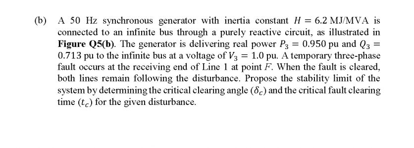
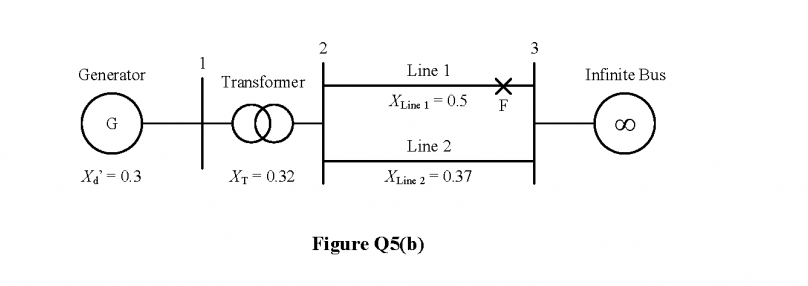
(b) A 50 Hz synchronous generator with inertia constant H = 6.2 MJ/MVA is connected to an infinite bus through a purely reactive circuit, as illustrated in Figure Q5(b). The generator is delivering real power P3 = 0.950 pu and Q3 = 0.713 pu to the infinite bus at a voltage of V3 = 1.0 pu. A temporary three-phase fault occurs at the receiving end of Line 1 at point F. When the fault is cleared, both lines remain following the disturbance. Propose the stability limit of the system by determining the critical clearing angle (8.) and the critical fault clearing time (tc) for the given disturbance.


Load flow analysis
Load flow analysis is a study or numerical calculation of the power flow of power in steady-state conditions in any electrical system. It is used to determine the flow of power (real and reactive), voltage, or current in a system under any load conditions.
Nodal Matrix
The nodal matrix or simply known as admittance matrix, generally in engineering term it is called Y Matrix or Y bus, since it involve matrices so it is also referred as a n into n order matrix that represents a power system with n number of buses. It shows the buses' nodal admittance in a power system. The Y matrix is rather sparse in actual systems with thousands of buses. In the power system the transmission cables connect each bus to only a few other buses. Also the important data that one needs for have a power flow study is the Y Matrix.
Types of Buses
A bus is a type of system of communication that transfers data between the components inside a computer or between two or more computers. With multiple hardware connections, the earlier buses were parallel electrical wires but the term "bus" is now used for any type of physical arrangement which provides the same type of logical functions similar to the parallel electrical bus. Both parallel and bit connections are used by modern buses. They can be wired either electrical parallel or daisy chain topology or are connected by hubs which are switched same as in the case of Universal Serial Bus or USB.


Trending now
This is a popular solution!

Step by step
Solved in 3 steps with 3 images


